Well, I see your point, and agree in general. But in that example with a component which it run hot because somebody thought that is enough a little heatsink, instead of a much bigger one, to run that device cool, and having better performances, I can not agree.
If you can remember, it were a similar case (and discussion) about the processor in 95, which it were running with a very poor own cooling system. The Oppo designers added an heatsink to the lower dissipation processor in 105 model...
My earlier remark were not meant to offend all the engineers out there. It were referred to that designed product.
Everybody has one time or another appreciated (based on some reasons) that somebody else did stupid things. That it not for sure meant that all the world is stupid... Agree?
Why not read it and understand the texts as it is, without unnecessary extrapolations?
Last edited:
The OPPO-105 is a technical tour de force.
Agreed. They really have upped the game in its standard form as it comes out of the factory. The clocking to the Sabre DAC is more careful and there are other subtle things. One I am not agreeing entirely with is the non-paralleling of the DAC's output phases, BUT it seems to work better with their post-DAC solution that it did in the '95, so you can't blame them for that.
But if somebody was after a stock '95 or '105 - then the added dollars of the '105 is worth it. Let's face, the number that are going to be modded or upgraded is very small.
I say it again - even to the phone enquiries I get - get the Oppo '105 even if you don't want to get it upgraded. It's great value for the money.
Cheers, Joe
The Oppo designers added an heatsink to the lower dissipation processor in 105 model...
It is an improvement, but there is still a positive 15V regulator that get rather more warmer compared to its negative 15V brother (sister?) next to it. Comes down to the fact that the negative is mainly only for the post-DAC circuit, whereas the +15V has to drive a lot of other things. But at least the cooling through the top panel is better too.
Cheers, Joe
I'm not arguing about the heatsink on the processor of 105. It is a good thing, and it should be there. It were in my earlier post about a design decision Oppo taken comparing with the older model. I should want actually a bigger heatsink for 105... Of course the chip itself is much improved, dissipate less and for sure it can run in parameters at much higher temperature. BUT running the processor as cool as possible it improve the picture a lot. I only still wonder why the designers of the device did not observed this fact.
The positive 15v regulator it still be used to generate AVCC for DAC and some other needed lower tensions. As the difference between 15v and the lower regulated ones is quite big, the dissipation it still be important. Anyway, I agree that on 105 it is an improvement over the 95 model. But the power supplies need better filtering, special the analogue 5v one. 150 - 170mV ripple on this 5V rail is quite much. I removed the headphone noise floor in my device by better filtering for PSUs...
The positive 15v regulator it still be used to generate AVCC for DAC and some other needed lower tensions. As the difference between 15v and the lower regulated ones is quite big, the dissipation it still be important. Anyway, I agree that on 105 it is an improvement over the 95 model. But the power supplies need better filtering, special the analogue 5v one. 150 - 170mV ripple on this 5V rail is quite much. I removed the headphone noise floor in my device by better filtering for PSUs...
Last edited:
I'm not arguing about the heatsink on the processor of 105. It is a good thing, and it should be there. It were in my earlier post about a design decision Oppo taken comparing with the older model. I should want actually a bigger heatsink for 105... Of course the chip itself is much improved, dissipate less and for sure it can run in parameters at much higher temperature. BUT running the processor as cool as possible it improve the picture a lot. /QUOTE]
Coris are you suggesting that the picture (as on the screen) would improve when the chip would be cooler?
jan
Yes, I would say so...
You know, the idea with a fan inside the box is not bead. The problem is that a such fan make noise... I have mounted a bigger heatsink for the processor. Now is more easy to do this, because the holes are already in place. But anyway, this task is not an easy one...
The basic idea here is that the processor it may run at the coolest temperature one can get (one way or another).
Last edited:
I can not imagine any effect of the chip temp (as long as it within the spec of course) on the picture rendering. Do you have any more information about that?
jan
It is not about picture rendering here... Rendering it is made in QDEO chip, based on the digital data coming/decoded from/in MediaTeck chip.
There is here about thermal noises which increase in a quite complex data chip`s stages, and generate electrical noises. Such noises it may be added to the useful data, and taken as data... An extra check and filtering it may be necessary to get rid of more often errors. This mean more processing time and filtering which it may filter or affect the useful data...
Those things are very much simplified here, but are a lot complex. You can judge this thinking at your processor in your computer. A such processor is specified at 90 - 100 dg.C, and it have to work at that temperature. Do you know what happen when you actually run your computer`s processor at 90dg.C? Or 80dg.C? Or 70dg.C for enough long time? You can only try yourself.
There is a quite simple rule here: running cool = running smooth. Running hot = running hard to get rid of errors first, then do the job it have to be done. More errors, more wasting time...
There is no any benefit for the job to be done, to increase (thermal)noises in a electronic device. This issue have to be prevented. About this I think we can agree. In opposite, there is benefit to run that device cooler as one can do.
Oppo 95 it had a very poor cooling solution. The chip itself could reach 60-70 dg.C in normal drift. After I mounted a better cooling system, and I lowered the temp to 40dg. C, I could notice the increasing in picture quality.
Oppo105 it have a heatsink mounted o n MediaTek, there is a lower dissipation processor, and the running temp (on heatsink) it is approx 50dg.C. Lowering this working temp for the processor even more it have impact in picture quality. This impact is not dramatic of course, but is reflected in a way that is not very easy to be described. The fine details are revealed better, the tonal and gradient in colors is changing in positive way, and so on. The picture to be designed on the screen get use of more detailed informations, and this it is noticeable.
The same thing it happen when one use another (better) oscillator for the main processor. The same thing it happen when one filter better the power in the system. What mean this? Removing/preventing the noises to get into the system in different ways and at different levels: cooling down the hot running components, less jitter on the clocks, more clean power for the devices.
All those things have impact, each in its domain, and the all together`s result is to be visualised on the screen and hearable on audio outputs... Increasing in quality is at last obvious!
Of course it may be difficult for (some)one "to imagine" something like this (above). When that someone goes through all those things, step by step, do it by himself one or another, then one not need to imagine something at all: is just experience it...
BTW, rendering is a digital processing based on special algorithms, noises in a system is about physics... Quite different things....
Last edited:
CMOS digital chips (almost all processors are made this way now) do behave differently over their operating temperature.
Mostly, the effects are related to the increase in channel resistance when hot. This effect can reach tens of percent; not negligible!
The increased channel resistance reacts with the capacitance of succeeding stages, and slows down transitions - with increasing temperature. This should be of no consequence, provided the design is properly timed in the first place, and the intended ambient temperature range is not breached.
However, in the converse, when cold, the lowered channel resistance increases transitional currents, which puts greater demands on local power supply decoupling.
Again, it should all be incorporated in the design - but differences may arise.
A system with degraded picture in cold ambients may have suspect supply design or decoupling.
I'm not saying any of this is happening here - but it's not impossible.
BTW, rendering is a digital processing based on special algorithms, noises in a system is about physics... Quite different things....
Indeed. That's why your long story about noise is irrelevant here.
jan
Indeed. That's why your long story about noise is irrelevant here.
jan
We can talk about rendering for your satisfaction... or to have a more relevant (for you) discussion. But it is a little bit out of topic in this thread/forum, I suppose.
I suggest you to try another forum. Thanks for visit us, and for your contribution.
Last edited:
Yes, for sure... Nobody say that is not working or the fault rate is unbearable, when about big production. We can not know actually what a fault rate it may be...
There is here about a commercial compromise price/quality. F. ex. a bigger heatsink it mean increasing cost production. And maybe a little bit more complicated mechanical design (in such case). What for if it is good enough performance for that money? But good enough performance it may not be equal to best performance... in all cases.
Such commercial/marketing appreciations are for sure not to apply only to Oppo`s products. This is a general point of view in business branches in such markets.
As it is Oppo player is good. It is a good basic product in the way to be a customized product, which it can improve even more its basic parameters.
Last edited:
Anybody has used the Oppo's build-in crossover? It sounds very, very good, although I miss separate outputs for L and R subwoofer.
What I cannot find in the documentation is what kind of filtering they are using. You can select the cross-over frequency but the filter type and slope is nowhere to be found.
jan
What I cannot find in the documentation is what kind of filtering they are using. You can select the cross-over frequency but the filter type and slope is nowhere to be found.
jan
Get into the few ohm world of DAC post processing...
I could see in the last time this information form an Dastin earlier post:
"For the output stage:
I dont think we ever claimed a current source, but rather a "current mode". The current mode is simply when the current going in and out the pin of the chip is sensed. This mode has the benefit of cancelling 2nd and 3rd harmonics of some of the internal ananlog circuitry. The "voltage mode" is when the pin of the chip has a voltage on it that is being sensed. While this has the 2nd and 3rd hormics (at the -100dB level or so), some people have even claimed this mode is more "tube-like" Its all personal prefference.
I hope this helps out a little.
Thanks
Dustin"
I have paid attention to the detail "current mode" very well explained/clarified here. The current mode it mean actually to make the chip outputs to use as much as possible current when outputting the differential analogue signals. It is known now the Joe`s transformer solution with paralleled 3 ohm resistors.
I thought to do the same, but using the I/V converter/op amp. So a I/V stage with 5 ohm converting resistor (I had no any 3 ohm for moment). I/V voltage reference 0V. The accordingly gain increase in next stage will compensate the low level signal out of such I/V setup.
Just impressive result! I`m very glad to get rid this way of the residual HF noise from DAC. No any such noises on RCAs in this case.
I have got quite big offsets on the final output (few hundred mV), and not equal on L/R. So I had to use coupling caps (Oppo`solution...") ). Have to work further to fix those resulting big offsets, but I`m very happy with the sound out of such setup. BTW, no any audible noise floor at all using a quite high gain for the final opamp. Very nice!
). Have to work further to fix those resulting big offsets, but I`m very happy with the sound out of such setup. BTW, no any audible noise floor at all using a quite high gain for the final opamp. Very nice!
Dustin knows for sure what he is talking about...
I could see in the last time this information form an Dastin earlier post:
"For the output stage:
I dont think we ever claimed a current source, but rather a "current mode". The current mode is simply when the current going in and out the pin of the chip is sensed. This mode has the benefit of cancelling 2nd and 3rd harmonics of some of the internal ananlog circuitry. The "voltage mode" is when the pin of the chip has a voltage on it that is being sensed. While this has the 2nd and 3rd hormics (at the -100dB level or so), some people have even claimed this mode is more "tube-like" Its all personal prefference.
I hope this helps out a little.
Thanks
Dustin"
I have paid attention to the detail "current mode" very well explained/clarified here. The current mode it mean actually to make the chip outputs to use as much as possible current when outputting the differential analogue signals. It is known now the Joe`s transformer solution with paralleled 3 ohm resistors.
I thought to do the same, but using the I/V converter/op amp. So a I/V stage with 5 ohm converting resistor (I had no any 3 ohm for moment). I/V voltage reference 0V. The accordingly gain increase in next stage will compensate the low level signal out of such I/V setup.
Just impressive result! I`m very glad to get rid this way of the residual HF noise from DAC. No any such noises on RCAs in this case.
I have got quite big offsets on the final output (few hundred mV), and not equal on L/R. So I had to use coupling caps (Oppo`solution...
). Have to work further to fix those resulting big offsets, but I`m very happy with the sound out of such setup. BTW, no any audible noise floor at all using a quite high gain for the final opamp. Very nice!Dustin knows for sure what he is talking about...
I was considering buying an OPPO BDP 105 . However this thread shows that people are hacking it quite a bit to get better sound. More so than any other Bluray machine I have seen lately. So does this mean that at $1.2K it still is an unoptimised design in the audio section ? I would have expected that OPPO has some very good audio circuit designers.
Why would one have to mod so much to make it 'better' especially after having paid $1.2K !
With a jump of almost double the price from the BDP103 , one would think they would have improved the sound so much that it would be tough to better that.
Why would one have to mod so much to make it 'better' especially after having paid $1.2K !
With a jump of almost double the price from the BDP103 , one would think they would have improved the sound so much that it would be tough to better that.
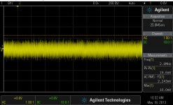
Well, I`ve got down to 2,5 ohm on I/V resistor, with x300 gain on final, for an useful signal of 2-3V (earlier standard player`s level). Noise on output is shown in the picture. Still have a quite high offset on outputs (-90mV and -40mV on L/R). A right AC coupling. I/V reference 0V. It seems to me that this offset is chip parameters depending. Bearable hearable hiss at 0,5m from the tweeter. Very nice and wide soundstage. It sounds really good, with high dynamics! But I do not like that hiss... I think to find a compromise setup. The idea with a very low I/V resistor it work at last very well.
Attachments
I was considering buying an OPPO BDP 105 . However this thread shows that people are hacking it quite a bit to get better sound. More so than any other Bluray machine I have seen lately. So does this mean that at $1.2K it still is an unoptimised design in the audio section ? I would have expected that OPPO has some very good audio circuit designers.
Why would one have to mod so much to make it 'better' especially after having paid $1.2K !
With a jump of almost double the price from the BDP103 , one would think they would have improved the sound so much that it would be tough to better that.
This about good Oppo machine or not (because the needed mods to increase its quality) it seems to be a never ending story...
This 105 model is better than the earlier. It have inside the ultimate DAC chip, and it have an exceptional video chip (Marvell QDEO). The Oppo designers are supposedly good, but it may be also some economical reasons too in designing of a commercial product. As it is BDP 105 is a good machine. Many people are satisfied with it. Few are not, and it modd it. A modded 105 player it can goes very high in quality, but it may cost a little bit more...
. A such customized machine could definitely not be sold as a commercial product by a company (Oppo). Or could it? Benefit of they who can do the mods... Some peoples are willing to pay the price to have the best... So it is actually.Well, I`ve got down to 2,5 ohm on I/V resistor, with x300 gain on final, for an useful signal of 2-3V (earlier standard player`s level). Noise on output is shown in the picture. Still have a quite high offset on outputs (-90mV and -40mV on L/R). A right AC coupling. I/V reference 0V. It seems to me that this offset is chip parameters depending. Bearable hearable hiss at 0,5m from the tweeter. Very nice and wide soundstage. It sounds really good, with high dynamics! But I do not like that hiss... I think to find a compromise setup. The idea with a very low I/V resistor it work at last very well.
Indeed that hiss is something you have to take care of. It's just above 60dB S/N with 2-3V out, very bad! Don't know which high dynamics you hear, but with the noise audible 0.5m from the speakers, it can't be much!
jan
- Home
- Source & Line
- Digital Source
- Oppo's BDP105 - discussions, upgrading, mods...