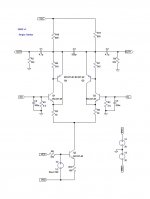
This is my minimalist I\V converter that i call UNIO.
It was designed based on the opinions i get from the other two thread that i start.
The almost universal opinion is that simple is better.
I have already build a prototype and i am very impress by the very good performance that this simple circuit produce.
This is intend to be use with a pcm1794a. but it can be redesign to work with others DAC.
the output voltage is 1Vrms in balanced mode or 0.5 Vrms non balanced.
Attachments
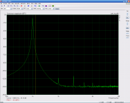
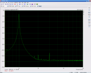
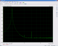
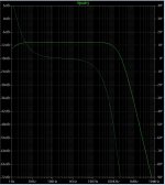
This is some distortion measurements of the prototype.
the first image is from the emu1212m alone ( the distortion is a little bit higher than normal because the low impedance load 565 ohm).
the second image is the output distortion with 0.7 Vrms
the third image is with 1Vrms.
This test was done with full balanced input and output.
the first image is from the emu1212m alone ( the distortion is a little bit higher than normal because the low impedance load 565 ohm).
the second image is the output distortion with 0.7 Vrms
the third image is with 1Vrms.
This test was done with full balanced input and output.
Attachments
The prototype was built with 5% resistors and polyester output capacitors.
And the power supply was not very good.
For better performance use 0.1% resistors in R1, R2, R5, R9, R17, R18.
C0G ceramic capacitors for C3, C4, C5
Polipropilene capacitors for C1, C2
And is very important to match the transistors. And of course use a very low noise power supply.
And the power supply was not very good.
For better performance use 0.1% resistors in R1, R2, R5, R9, R17, R18.
C0G ceramic capacitors for C3, C4, C5
Polipropilene capacitors for C1, C2
And is very important to match the transistors. And of course use a very low noise power supply.
On what level is the DC offset at the input ?
why do you ask for the input offset? because of the PCM1794 output protection diodes, or there is another reason ?
Thanks zxgravediggerxz .
I don´t know if i understand your question, can you be more specific. What is the difficulty you have ?
I use a emu1212m sound card.
sorry for not being clear.
I was just referring to the physical setup of your measurement system. For example you are using your emu1212m sound card to output signals to your dac? and than you put the I/V stage output to your emu1212m input?
zxgravediggerxz,
The test was made with the I/V converter only.
The emu1212m is a fully differential input and output sound card.
I have connect the inputs of the sound card to the outputs of the I/V converter.
And the output of the emu1212 to the input of the circuit, this sound card has a output resistence of 560 ohms per phase. with a sound card that dont have this resistence in the output one must use a serie resistence to simulate a current DAC.
When I finish the DAC that will be modular, I will perform another test but this time using only the inputs of the emu1212m and the spdif output connected to the DAC.
The ARTA program seems very good. It was the first time i use it.
Hi Dirk.
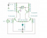
This type of connection between the npn and the pnp transistor is a old technique called a Sziklai pair, named after his inventor George C. Sziklai.
Its a very good technique for improving the linearity of a simple transistor. You can google for it, if you are interested.
And yes the current to voltage convertion is made by a pair of 5.6 ohms , remember the post from Ken Newton when he said that he uses a 150 ohms passive I/V with very good results, so i think a 5.6 ohms is a good solution.
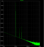
Just for curiosity, i post here the simulated fft, as one can see the simulation is very similar with the actual measurements made with a real circuit.
I realy think that the LTspice is a very powerfull tool to develop a circuit, and if someone is interested in learning electronic my advice is to use a simulator, is no better and faster way than to use a spice simulator
I realy think that the LTspice is a very powerfull tool to develop a circuit, and if someone is interested in learning electronic my advice is to use a simulator, is no better and faster way than to use a spice simulator
Attachments
Hi Dirk.
This type of connection between the npn and the pnp transistor is a old technique called a Sziklai pair, named after his inventor George C. Sziklai.
Its a very good technique for improving the linearity of a simple transistor. You can google for it, if you are interested.
And yes the current to voltage convertion is made by a pair of 5.6 ohms , remember the post from Ken Newton when he said that he uses a 150 ohms passive I/V with very good results, so i think a 5.6 ohms is a good solution.
OK, I didn't recognize it, obviously, though I've read about the Sziklai pair before. It's mostly used in output stages instead of a Darlington.
So, we should be seeing about 43mV p-p at the bases of Q1 and Q2.
This is a very interesting solution, thanks. I tried an IV stage with common base Darlingtons connected as current mirrors (with pull down resistors) like the Leach circuit but it wasn't as good as the other circuit I used. I tried something similar with opamps but the distortion was worse than with a pure transistor IV converter.
For me, it seems to be a toss up between the Leach current mirror common base circuit and a zero field input transformer circuit using a LME49990. Right now I'm leaning towards the zero field circuit because the results are more predictable using a chip than with discrete transistors, at least for an amateur like me.
My Tina software seems to give higher distortion results in my simulations than what I read in, for example, Walt Jung's results. I've simulated his circuits and I don't get as good results. I don't know if it's Tina or the spice models I'm using. I've even modeled circuits shown here in Tina and I get worse THD than others simulating with LTSpice. go figure.
Last edited:
Hi Sergio
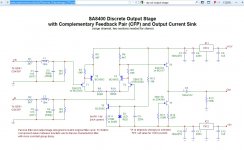
Have You seen that...?
http://www.raylectronics.nl/pdfs/Discrete_Outputstage_CFP.pdf
Rosendorfer
Have You seen that...?
http://www.raylectronics.nl/pdfs/Discrete_Outputstage_CFP.pdf
Rosendorfer
Attachments
- Status
- This old topic is closed. If you want to reopen this topic, contact a moderator using the "Report Post" button.
- Home
- Source & Line
- Digital Source
- UNIO a minimalist I/V converter