Why not have the board with a jumper bypass option and no buffer components installed for those that don't need it?
Cheers George
Adding the space in pcb for the buffer will increase the PcB cost in 50%, I want this circuit to be high quality but also accessible , but I agree that including the buffer has benefits. So it will be added a modified diamond buffer that have a linearity suitable for this project (less than 0.0001% distortion) without feedback loop. buffer will be in a auxiliary PcB that can be connected in the main pcb. this way the main PcB will be more accessible and we can experiment with others buffer like the one that Joachim and MiiB present that is also a very good solution.
Last edited:
I would like it included, as you can imagine myself and my customers are driving into a low impedance Lightspeed Attenuator. Why not have the board with a jumper bypass option and no buffer components installed for those that don't need it?
Cheers George
I would like the buffer on the same pcb but draw in a way that it can be omitted just not soldering the components there (so kind of double output point). Simple enough? If alex_mm will do the pcb should be easy cake for him.
+1
")
Telstar, I will be the one that makes the pcb.
I didnt mean to diminish your skills, sorry.
It doesn't matter where you connect the servo, it is -always- in the audio
path. Over the years this discussion has come up repeatedly.
The servo has to adjust the -audio- OP DC level and do so by integrating
the audio itself. Every servo works this way, you can connect them wherever
you like but if they are to work, they are in the audio path.
As such they definitely are audible and can often sound worse than a good
coupling cap. I know people who have in fact gone to extreme lengths to
make the servo truly out of the circuit, one worked on heat feedback and
another was a sampling system which made small adjustments at pre defined
time intervals, otherwise being off.
Just socket the opamp and try swapping it - you might get a surpise
George,
The optimum value of the LPF cap will probably be system / DAC dependent.
You might even get away without one, if the I-V is stable as such. The
1704 has low OOB noise.
WRT the 2k OP resistor, I would first try this I-V without an OP buffer.
It may well sound better 'in the raw' so to speak.
The issue with OP buffers is you will be hard pressed to find a design that
preserves the linearity of this I-V's super low distortion.
It will almost certainly require some sort of bootstrapping.
I agree that the servo will always be in the audio path just as the power supply is. There is a trick to simulate the dB level of the servo vs frequency. Its not uncommon to find that an an open loop I/V design with a servo has significant feedback up to midbass . There is a model posted on this forum somehwere. May want to have the option to go sans servo and use a cap.
As far as a buffer, I guess I always think of a buffer following an I/V as an opportunity to make a nice filter in between. Its good that you are planning a separate buffer panel so folks have that option.
This is great stuff. Thanks for sharing.
qusp, I do not know any device that only produce 2° harmonic, the buffer that I was talking also product 3° harmonic but at 33 db lower level. if one has careful the third will be bellow noise floor. It is only a mosfet BS170 in single end with a ccs of 15ma and a load of 1k ohm, I have choose BS170 because it produce 10 time more distortion than a bjt.
I agree that the servo will always be in the audio path just as the power supply is. There is a trick to simulate the dB level of the servo vs frequency. Its not uncommon to find that an an open loop I/V design with a servo has significant feedback up to midbass . There is a model posted on this forum somehwere. May want to have the option to go sans servo and use a cap.
As far as a buffer, I guess I always think of a buffer following an I/V as an opportunity to make a nice filter in between. Its good that you are planning a separate buffer panel so folks have that option.
This is great stuff. Thanks for sharing.
Regal, If I understand what you are telling , you say that if a opamp has 110 DB of open loop gain for example , the filter should have at least 110db of attenuation at audio frequencies ? I will investigate this. I will see if I have time to simulate the frequency response of the servo.
I have made some simulations to see the frequency response of the servo, and some alterations to prevent the servo from having feedback at audio frequencies.
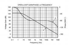
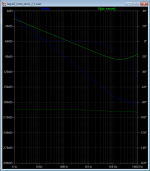
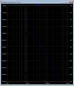
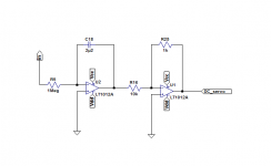
The first image is the open loop of opa2134 , the second is the FR before the modifications, third is FR with modifications, the last is the modifications in R25 and C18.
with the modification the servo does not have excess gain to have feedback above 40hz , if we decrease R25 to 200ohms this value decrease to 20hz.
in second image in green there is th FR of the servo with only one pole, in this way the servo has excess gain to have feedback until 1000 Hz , with two pole servo this value is much lower (blue).
Attachments
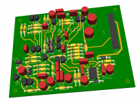
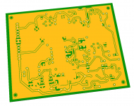
3D images of the board , but i have to do some modifications , change some traces from bottom to top to have a wider ground superficie in bottom, and add some connectors to input output and power, hope i have time this night to finish it.
Attachments
smms,
It seems you can route more wires on components side, not to devide ground plane.
the circuit conveys input current to output, and the current flows to ground through the IV resistor and paralleled capacitor, so it may be some benefit to separate ground return pass and ground plane.
It seems you can route more wires on components side, not to devide ground plane.
the circuit conveys input current to output, and the current flows to ground through the IV resistor and paralleled capacitor, so it may be some benefit to separate ground return pass and ground plane.
Yes Shinja, I have already changed some traces to the top side as i said in post #692.
I have take attention to the ground currents paths and the inductance of ground , important is to get the currents of the rail capacitors away from the path of the signal, there is no need to separate the ground.
I have take attention to the ground currents paths and the inductance of ground , important is to get the currents of the rail capacitors away from the path of the signal, there is no need to separate the ground.
Last edited:
Im not that good to express myself, especially in English
I will separate the ground return of the rail capacitors from the rest of the ground .
This weekend will be the audioshow in Lisbon so I will not have much time left , but I hope next week to have 2 prototype board made.l am very curious to listening the final results of all of this.
I will separate the ground return of the rail capacitors from the rest of the ground .
This weekend will be the audioshow in Lisbon so I will not have much time left , but I hope next week to have 2 prototype board made.l am very curious to listening the final results of all of this.
- Status
- This old topic is closed. If you want to reopen this topic, contact a moderator using the "Report Post" button.
- Home
- Source & Line
- Digital Source
- dac I/V convertion with very low distortion