You can find tons of info via google on LP filters for DAC.
Why do we use low pass filter after DAC ?
http://www.diyaudio.com/forums/digital-line-level/151934-dac-output-filters-need-explanations.html
Digital-to-analog converter - Wikipedia, the free encyclopedia
Reconstruction filter - Wikipedia, the free encyclopedia
Patrick
Why do we use low pass filter after DAC ?
http://www.diyaudio.com/forums/digital-line-level/151934-dac-output-filters-need-explanations.html
Digital-to-analog converter - Wikipedia, the free encyclopedia
Reconstruction filter - Wikipedia, the free encyclopedia
Patrick
I did a sim and your idea affects the frequency response of the circuit more than the distortion - the capacitors you suggest act like extra Civ. I don't know whether they'd help with RFI.
My solution is just to put it in an enclosure. I get the results I posted in #1069 which I think are good enough and the original Sen is better for noise than my variant so you should expect better.
I can get better results than those of #1069 if I reduce RM - noise goes down and distortion goes up a little.
I agree. I made the suggestion before I simulated the effects on my circuit.
I think one good way is just to put a good RF capacitor across the 18V supply.
But, speaking of using batteries for the 18V supply, I believe a regulator is required anyway since two "9V" batteries will not produce exactly 18V. The actual voltage of batteries varies a lot (7.2V to 9.6V for example), depending on the type and the state of charge, so the distortion and voltage output for the circuit will change a lot with batteries. I don't see a problem with floating a regular power supply for this purpose.
To be honest I am not surprised at all.
I do not consider it necessary to use a source follower to drive the gates.
Tying them to Gnd or to the Vref divider for ES9018 as I posted is low impedance enough.
You made thing worst by running the Source Follower off the floating PSU.
This introduces an additional capacitive path of current to Gnd as the rail swings with signal.
This was not there originally and IMHO destroys the beauty of the circuit.
If you have to do this then the source followers should have split-rails referenced to Gnd, meaning yet more additional power supplies.
But for an academic experiment, I thought it would make a good exercise.
Just to show you simulation does not replace human thinking.
Patrick
yes Dirk, but the actual working voltage of batteries IS pretty stable and does not vary anywhere near that much. most batteries will drop fairly rapidly from their fully charged state (which is above the nominal voltage) in the first short while, then remain pretty steady for ~75% or more of their charge, dropping a fairly small amount, then drop rapidly again at the end of their cycle.
At such low discharge rates as we are using here, they are MUCH more flat again; use them within their plateau and cut off before the sharp drop.
At such low discharge rates as we are using here, they are MUCH more flat again; use them within their plateau and cut off before the sharp drop.
To be honest I am not surprised at all.
I do not consider it necessary to use a source follower to drive the gates.
Tying them to Gnd or to the Vref divider for ES9018 as I posted is low impedance enough.
You made thing worst by running the Source Follower off the floating PSU.
This introduces an additional capacitive path of current to Gnd as the rail swings with signal.
This was not there originally and IMHO destroys the beauty of the circuit.
If you have to do this then the source followers should have split-rails referenced to Gnd, meaning yet more additional power supplies.
But for an academic experiment, I thought it would make a good exercise.
Just to show you simulation does not replace human thinking.
Patrick
The plan with #998 was to take the gate leakage current of the earlier JFETs and feed it back into the last pair of JFETs which work like another small Sen instance to convey the gate leakage current of the earlier JFETs into Riv leaving only the gate leakage current of the last JFET which is much smaller anyway because the voltage across that gate doesn't swing so much. Thus running the last pair off the same floating PSU was intentional.
I think it's quite elegant ;-) and I think the simulation results show that it does work to reduce distortion (-200dB 3rd with 256R Riv).
I think it sounds bad because the bandwidth is too wide - simulation shows 100MHz - so I think it just passes all the DAC noise and it's probably picking up RFI too. I can't measure anything above 96kHz so I don't know.
Maybe it could be tweaked for success with a capacitor somewhere. Civ is too late - for a circuit to sound good I think you need to stop inaudible frequencies from getting into it rather than filter them out afterwards.
I think it's quite elegant ;-) and I think the simulation results show that it does work to reduce distortion (-200dB 3rd with 256R Riv).
Your sim results will be very good with current sources as inputs. Unfortunately, they will also bear little relevance to actual use with DACs, whose "current outputs" can be as low as a few hundred ohms, and moreover may interact with the codes. Also, cancellation of even-order is fine and dandy, but its efficacy depends very much on component matching. In addition, I doubt that the models include signal-induced self-heating, which will spoil things well before -200dB is reached.
Your sim results will be very good with current sources as inputs. Unfortunately, they will also bear little relevance to actual use with DACs, whose "current outputs" can be as low as a few hundred ohms, and moreover may interact with the codes. Also, cancellation of even-order is fine and dandy, but its efficacy depends very much on component matching. In addition, I doubt that the models include signal-induced self-heating, which will spoil things well before -200dB is reached.
I measured -100dB for 2nd and 3rd on the real #998 circuit which seems to be the limit of the analog part of my measuring circuit - so it works OK (apart from the sound!). I wasn't expecting to achieve -200dB; I just wanted to fix the distortion of Sen at high frequencies. #908 works for this and sounds good (at least with 1.2k RM which I still have left over from experiments with #998).
I think maybe a resistor (10k ish) between the gates of the first set of JFETs and the last pair might fix #998.
Do you know what the output impedance of the DAC you are using is?
I do like the idea of correcting for displacement currents in the basic input section without requiring additional voltages. But the problem the approach poses for matching is formidable.
I will post soon, probably in a separate thread, on a repurposing of some of the parts, along with cascode structures, which seems to my Mahayana sentiments, still pretty Zennish. And it's all free range NJFET")
Brad
I do like the idea of correcting for displacement currents in the basic input section without requiring additional voltages. But the problem the approach poses for matching is formidable.
I will post soon, probably in a separate thread, on a repurposing of some of the parts, along with cascode structures, which seems to my Mahayana sentiments, still pretty Zennish. And it's all free range NJFET
Brad
Do you know what the output impedance of the DAC you are using is?
I do like the idea of correcting for displacement currents in the basic input section without requiring additional voltages. But the problem the approach poses for matching is formidable.
I will post soon, probably in a separate thread, on a repurposing of some of the parts, along with cascode structures, which seems to my Mahayana sentiments, still pretty Zennish. And it's all free range NJFET
Brad
Not sure on the PCM1794A output impedance. Think it is quite low - maybe 1K ish.
With #998 (and to a lesser extent #908) you can parallel up pairs of JFETs to get the I/V input impedance down as far as you like without making the distortion worse since the gate current to ground doesn't increase.
Matching wasn't any harder than for Sen - I just picked pairs that were matched to .01 mA Idss.
I think the problem is high frequency noise - I think it does a bad job rejecting noise coming in from the output and it may have been oscillating at high frequency I'm not sure.
I have a wireless mouse and I did notice that when #998 was switched on I was getting two mouse clicks registered every time I pressed the button - that can only be a bad sign.
I'll try adding a resistor to see if I can calm it down a bit.
yes Dirk, but the actual working voltage of batteries IS pretty stable and does not vary anywhere near that much. most batteries will drop fairly rapidly from their fully charged state (which is above the nominal voltage) in the first short while, then remain pretty steady for ~75% or more of their charge, dropping a fairly small amount, then drop rapidly again at the end of their cycle.
At such low discharge rates as we are using here, they are MUCH more flat again; use them within their plateau and cut off before the sharp drop.
Well, if the actual voltage isn't that critical to your design, then batteries could be ok I guess. They still produce noise though. They are not noise-free.
Also, I was under the impression that the jfets in this design were running at Idss, which for these is anywhere north of 10mA. You'd double that for paralleled jfets of course. The rechargable 9V batteries have anywhere from 100 something mAH to over 500, so that's something like 10 to 50 hours of running, but towards the end the voltage drops dramatically. I assume the plateau is far shorter than that.
So, I don't see the attraction to batteries, sorry.
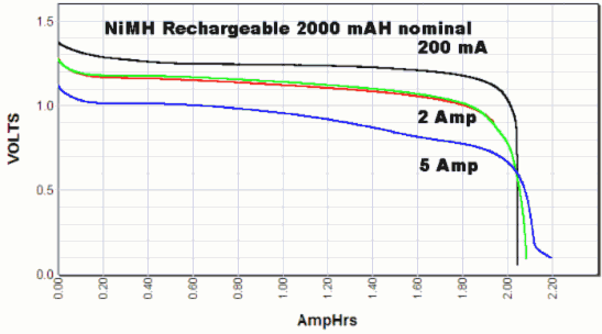
actually no, the plateau at this low current is the majority of the charge, only at the very end. at the risk of enraging Patrick i'm just going to link an image. at such low current the drop is much more severe, it will be almost flat and then drop like a stone at 10-20ma, its really not worth worrying about.
the attraction to batteries is avoiding all of the issues that have been discussed over the last however many pages. they come with their own issues of course, but they have plenty of advantages and the vdrop is a complete non-issue in this build.
of course they arent noise free, but the noise is very low and there is a complete lack of mains ripple
Here's an article on batteries vs. regulated supplies:
Simple Voltage Regulators Part 1: Noise
This particular circuit (Zen, etc.) is sensitive to the output impedance of the floating supply. Unless the batteries are heavily bypassed, the source impedance will have a negative effect on the performance of the circuit. The circuit requires that the floating supply cancel out all differential mode signals and the only way to do that is to make sure it is a dead short for AC signals.
I do not know where you are getting 9 volt batteries with that high of an amp hour rating. According to Wikipedia, these kinds of batteries have much lower amp hour ratings:
Nine-volt battery - Wikipedia, the free encyclopedia
Please note that I am talking about ordinary 9 volt batteries, not huge and very powerful battery packs made from a bunch of high capacity NiMH cells. I think it's plainly obvious that hooking up say a 12 volt car battery to this circuit is not going to have an issue with a 10-20 mA load.
Last edited:
> This particular circuit (Zen, etc.) is sensitive to the output impedance of the floating supply.
I am sorry, but the SEN / CEN IV are completely different circuit principle than the ZEN IV, as already explained in the article.
> Unless the batteries are heavily bypassed, the source impedance will have a negative effect on the performance of the circuit.
> The circuit requires that the floating supply cancel out all differential mode signals and the only way to do that is to make sure it is a dead short for AC signals.
Really ?
BTW, have you actually built and tested one ?
Cheers,
Patrick
I agree - I also see absolutely no attraction to batteries.So, I don't see the attraction to batteries, sorry.
However, with SEN I so very clearly hear the attraction to batteries, that I am considering to implement them much more frequently in my builds.
I agree - I also see absolutely no attraction to batteries.
However, with SEN I so very clearly hear the attraction to batteries, that I am considering to implement them much more frequently in my builds.
Yes, the subtle benefits are significant. And with cascode structures, although the voltage burden is higher, the noise in the batteries is virtually irrelevant.
It amuses me a bit to see people complaining about the hazards of noise pickup with batteries, yet claiming that floating mains-powered supplies should be trivial. It's true that with great care and lots of good common-mode chokes, mains supplies can be sufficiently good --- but it's a lot of trouble.
Actually Nic, you can do an experiment for us.
Add a series resistor to the battery between +V battery and +V circuit.
Say 1R.
Run the SEN IV to play music (or signal).
Measure the differential voltage across the 1R resistor.
(You need a differential probe or 2 scope channels and then subtract.)
I bet you will see DC only.
The circuit is designed such that the current draw on the batteries are constant ( = Idss of matched FETs).
And then you can also listen for any "detrimental" effects of the 1 ohm resistor.
Must be a very poor battery with internal resistance of 1 ohm !!!
Patrick
I agree - I also see absolutely no attraction to batteries.
However, with SEN I so very clearly hear the attraction to batteries, that I am considering to implement them much more frequently in my builds.
Me too. It's only 375 cells to get B+ for my amp!
Here's an article on batteries vs. regulated supplies:
Simple Voltage Regulators Part 1: Noise
This particular circuit (Zen, etc.) is sensitive to the output impedance of the floating supply. Unless the batteries are heavily bypassed, the source impedance will have a negative effect on the performance of the circuit. The circuit requires that the floating supply cancel out all differential mode signals and the only way to do that is to make sure it is a dead short for AC signals.
I do not know where you are getting 9 volt batteries with that high of an amp hour rating. According to Wikipedia, these kinds of batteries have much lower amp hour ratings:
Nine-volt battery - Wikipedia, the free encyclopedia
Please note that I am talking about ordinary 9 volt batteries, not huge and very powerful battery packs made from a bunch of high capacity NiMH cells. I think it's plainly obvious that hooking up say a 12 volt car battery to this circuit is not going to have an issue with a 10-20 mA load.
I posted the graph to simply show the discharge curve of NIMH and how radically it changes with lower currents and I fail to see how a higher capacity battery will behave any differently at such low currents. myself I use much higher current single cell lifepo4 cells that put the above graph to shame as far as current, but NIMH are no slouches either. basing your argument on zero experience and decades old research is pretty meaningless i'm afraid.
I wonder when people who have no experience of using quality batteries in their gear will stop quoting that article to back up their present day arguments? its getting pretty tiresome, the number of times its been covered is right up there. I dont have the gear to test or I would be answering the call to update it.
also notice the voltage scale on the side, this is not a big battery
AC and batteries and switching supplies all have pros and cons, areas they do well and others where each is a pita, but low current low noise line level gear is most definitely an area where batteries excel
Last edited:
- Home
- Source & Line
- Digital Line Level
- Zen -> Cen -> Sen, evolution of a minimalistic IV Converter