Joachim,
See here for the PCB layout of the full balanced version.
Only need minor adaption to get to post#1034.
http://www.diyaudio.com/forums/anal...sign-high-end-tone-control-2.html#post2978112
Patrick
See here for the PCB layout of the full balanced version.
Only need minor adaption to get to post#1034.
http://www.diyaudio.com/forums/anal...sign-high-end-tone-control-2.html#post2978112
Patrick
diff to SE converter
Try this.
I just trashed a longer text before sending so I'll follow up later.
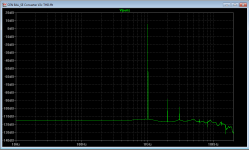
As shown though, sims indicate 17ppm mostly third with 2mA p-p each input to 15th harmonic, 40MHz -3dBr before additional capacitive loading. Use good current sources.
Try this.
I just trashed a longer text before sending so I'll follow up later.
As shown though, sims indicate 17ppm mostly third with 2mA p-p each input to 15th harmonic, 40MHz -3dBr before additional capacitive loading. Use good current sources.
Attachments
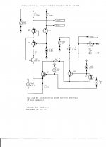
This is a low impedance input design. I/U and bal-unbal converter all in one. If this is not Zen then i am no christ.
Joachim, that was my initial intent, but to my surprise it, in fact, has an input impedance (each input to common) of almost exactly the value of either R3 or R4! This odd configuration of a Wilson mirror is a bit counter to intuition. But it does work (in simland) rather well. Q2 may not be necessary, it was there when I was building the thing up and looking at the output before the common-base turnaround stage. The Boxall pair (Q6 and Q7) was added to reduce the signal-induced thermals in Q1.
Of course the output can be buffered for driving longer lines, and R1 can be adjusted to provide more or less gain. But with 100pF of loading C the -3dBr bandwidth is still a healthy ~800kHz, so I'm not sure I would bother with a buffer.
When I add the plethora of current generators of adequate quality the thing won't look so simple anymore
 And then the various voltages are a nuisance. But I think fun nonetheless. The input d.c. potentials are about at common.
The CMR is also very good, with R3 and R4 matching the most critical. About 104dB below the equivalent differential signal at 1kHz, 3dB worse at 3.5kHz, and at 20kHz still about 89dB, and continuing to rise after that.
Brad
EDIT: It's even a little weirder that that. In a distant analogy to everyone's favorite four-resistor single opamp differential amp, the impedance at Q3 when driven alone is indeed a low common-base-stage one. Driving Q4/R4 alone is about 1k. When driven differentially the two inputs look like 1k each to common.
Last edited:
And still a little weirder: Driven differentially, the impedance at R3/Q3, when R4/Q4 is driven by the equal-magnitude opposite-polarity current, appears to be negative; that is, the voltage is opposite in polarity to what would be expected from a resistor. This is because the voltage at R3/Q3 follows the voltage at R4/Q4. And yet, assuming current drive, the current still is properly accepted and subtracted from the other current.
Results with finite output Z current sources may vary.
I need to build this.
Results with finite output Z current sources may vary.
I need to build this.
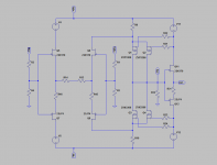
I declare myself happy with this.
It now has much lower bias in the second stage (20mA compared to 70mA before).
So all devices are TO92 or similar. And performance is still excellent.
Next step PCB layout. Low priority though.
Patrick
It now has much lower bias in the second stage (20mA compared to 70mA before).
So all devices are TO92 or similar. And performance is still excellent.
Next step PCB layout. Low priority though.
Patrick
Attachments
Balanced to Single Ended Conversion to be continued in new thread :
http://www.diyaudio.com/forums/anal...anced-single-ended-converter.html#post3099429
Patrick
http://www.diyaudio.com/forums/anal...anced-single-ended-converter.html#post3099429
Patrick
- Home
- Source & Line
- Digital Line Level
- Zen -> Cen -> Sen, evolution of a minimalistic IV Converter