27V is OK if your JFETs can handle the dissipation (=27/2*Idss).
So that depends on the Idss.
Patrick
Thanks. I am working on it.
I have a Sen All Jfet IV converter, I want to know if can be modified to use as ouput stage for No Dac (direct DSD from USB-I2S board).
http://www.diyaudio.com/forums/digital-line-level/273474-best-dac-no-dac.html
http://www.diyaudio.com/forums/digital-line-level/273474-best-dac-no-dac.html
Attachments
I have a Sen All Jfet IV converter, I want to know if can be modified to use as ouput stage for No Dac (direct DSD from USB-I2S board).
http://www.diyaudio.com/forums/digital-line-level/273474-best-dac-no-dac.html
The Sen is an I/V converter. For the No Dac you need a (passive filtered) buffer. Have you considered the JG Filter-buffer?
I need X4 amplification.
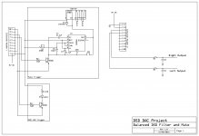
This is a discussion for the no-dac thread. Consider the version with flip flop and balanced output. The output level of the flip flop is higher and can probably be modulated by the supply voltage.
Or, use a preamp.
Behavior as a DAC clock frequency goes up?
As the DAC clock frequency goes up, what are the considerations regarding the jfet bandwidth? I am looking at DSD applications with clock in the 45Mhz range. My initial thought is that input capacitance would be a "good thing" because we want to filter out the clock following the I-V stage in any case. Is there any reason to be concerned about non-linearities (not in the LTSpice models) that might cause intermodulation distortion? Cascoding should improve bandwidth but how necessary?
As the DAC clock frequency goes up, what are the considerations regarding the jfet bandwidth? I am looking at DSD applications with clock in the 45Mhz range. My initial thought is that input capacitance would be a "good thing" because we want to filter out the clock following the I-V stage in any case. Is there any reason to be concerned about non-linearities (not in the LTSpice models) that might cause intermodulation distortion? Cascoding should improve bandwidth but how necessary?
My initial thought is that input capacitance would be a "good thing" because we want to filter out the clock following the I-V stage in any case.
One issue with capacitance here is that when you have an unipolar signal (like between 0V and some pos V like +5 or +3.3) feeding that into a cap will cause DC offset due to averaging.
The averaging is a Good Thing but the offset may be an issue.
Jan
Best to simulate in Spice.
I did, and posted my model. It seems to be linear into the low Mhz range with a falloff of ~10db at 10Mhz, and on as expected. I thought this would be perfect using a 22-44Mhz clock (DSD512 - 1024). In a discussion of the merits of discrete vs op amp based I-V, it was proposed by a couple of people whom I respect that these clock rates might give problems for discrete circuits ...
Didn't make sense to me but there are many things I don't know and just wanted to check e.g. the Spice models may not be accurate above certain frequencies etc.
What is the structure of the DSD device output?As the DAC clock frequency goes up, what are the considerations regarding the jfet bandwidth? I am looking at DSD applications with clock in the 45Mhz range. My initial thought is that input capacitance would be a "good thing" because we want to filter out the clock following the I-V stage in any case. Is there any reason to be concerned about non-linearities (not in the LTSpice models) that might cause intermodulation distortion? Cascoding should improve bandwidth but how necessary?
As far as cascoding, it improves performance almost without pain. And for the use of the reigning high gain-bandwidth BF862, you want to use it to keep the input device drain-gate voltage down and dissipation low. With a sufficiently tight layout the grounded-gate approach will beat most integrated solutions, particularly as op amps start out with a nonoptimal high input impedance which is only reduced with shunt feedback. Barrie Gilbert may have exaggerated the situation a little, but stated that an op amp was a bad idea (he may even have said The worst!) to use as a I-V converter. Yet, just about everybody does.
I recall an AES discussion many years ago in which Keith O. Johnson got the mic and said DSD was an almost irresponsible approach, as it was bound to be handled badly by power amps.
What is the structure of the DSD device output?
Using the DSC1: http://www.diyaudio.com/forums/digital-line-level/254935-signalyst-dsc1.html, there is a shift register based FIR filter with 32 lines each with a 15k resistor. So 5 or 3.3 volts depending on the logic family being used.
Thanks. Not wanting to go through that thread at the moment, does anyone suggest a better power supply than the LM1086-based regulators? In addition to a superior I-V converter, that would seem to be an area of opportunity for improvement.Using the DSC1: http://www.diyaudio.com/forums/digital-line-level/254935-signalyst-dsc1.html, there is a shift register based FIR filter with 32 lines each with a 15k resistor. So 5 or 3.3 volts depending on the logic family being used.
One thing I like: if the outputs of the shift registers are always active (not tri-state floating), the output Z of the connected plurality of resistors is fairly constant with code, unlike a number of so-called current output DACs. This will entail less distortion due to I-V converter input impedance interacting with the source impedance.
What would work well would be a complemented code loaded into duplicate shift registers to make the voltage regulator current drains constant except for the switching transitions. For a +5V LM1086 the output noise in a 10Hz to 10kHz bandwidth is about 150uV, so either quieter regulators or more passive filtering would be good, and the latter could be achieved if the current drain is constant. The plurality of regulators helps a little too.
EDIT: I read through most of the thread and see that most of what I speculated about has been covered.
Last edited:
By the way, sims show the basic floating-supply current conveyor with 862 and 111 and a 1k load to have a -3dB bandwidth of about 115MHz. If one wraps a simple complementary common-emitter stage around the input device to further reduce input impedance using medium-speed bipolars, the bandwidth goes up a bit to 167MHz. Sounds promising. I'd probably parallel a couple more 862s and 111s to have the standing current a bit larger, as with the 32 15k resistors the peak current for a string of logic 1s would be about 10.7mA into a virtual ground.
By the way, sims show the basic floating-supply current conveyor with 862 and 111 and a 1k load to have a -3dB bandwidth of about 115MHz. If one wraps a simple complementary common-emitter stage around the input device to further reduce input impedance using medium-speed bipolars, the bandwidth goes up a bit to 167MHz. Sounds promising. I'd probably parallel a couple more 862s and 111s to have the standing current a bit larger, as with the 32 15k resistors the peak current for a string of logic 1s would be about 10.7mA into a virtual ground.
Not sure what is wrong with my LTSpice model then as I am seeing falloff at 10Mhz?
So 3 parallel bf862s are ok with 3.3V logic then? Each bf862 is best at no more than 2mA?
The nominal Idss of 862s is around 15mA, a bit lower at the lower Vds with cascoding. With the basic topology, without any input servoing, the performance is best the lower the current swing per 862.Not sure what is wrong with my LTSpice model then as I am seeing falloff at 10Mhz?
So 3 parallel bf862s are ok with 3.3V logic then? Each bf862 is best at no more than 2mA?
My load resistance for those bandwidth numbers was 1k. A very small shunt capacitance was used, but for direct use with typical cabling etc. the bandwidth will plummet. However this does not mean anything bad happening as far as how well the input terminates the output of the paralleled shift register resistors, since it is not a conventional I-V converter using a lot of loop gain and shunt feedback to produce a low input impedance.
In fact you will, sooner or later, want to limit the output bandwidth in most any conceivable audio application.
- Home
- Source & Line
- Digital Line Level
- Zen -> Cen -> Sen, evolution of a minimalistic IV Converter