Getting closer...

where Is sen placed
If you scroll the thread there are other pictures of this build where things are more clear.
The digital source is an Amanero board that goes to a I2S-PCM board (Ian). The latter feeds two AD1865 DAC, one per channel to get a balanced output.
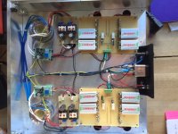
On the PSU side each channel has his own transformer that feeds a Super regulator for the analog supplies of the DAC and a TPS7A4700 for the digital supply. The IV are fed with four couples of 9V batteries. Next to each IV there is an LC filter; this is the big cap you see.
Attention has been put in the case layout. I wanted to achieve the same benefit of a dual case with one box, so I came with the idea of a kind of drawer with the AC part on the bottom and the DC and signal part on the top. All the rectification is done in the bottom layer. The batteries are charged with an external 19V laptop PSU when the DAC is off. There is a relays system that do that.
My slow plan was to build two sen dacs, one with the AD1865 and the second one with ESS9018. The idea is to develop two platform that are transparent enough on the analog side and to start playing with the digital side later.
D.
The digital source is an Amanero board that goes to a I2S-PCM board (Ian). The latter feeds two AD1865 DAC, one per channel to get a balanced output.
On the PSU side each channel has his own transformer that feeds a Super regulator for the analog supplies of the DAC and a TPS7A4700 for the digital supply. The IV are fed with four couples of 9V batteries. Next to each IV there is an LC filter; this is the big cap you see.
Attention has been put in the case layout. I wanted to achieve the same benefit of a dual case with one box, so I came with the idea of a kind of drawer with the AC part on the bottom and the DC and signal part on the top. All the rectification is done in the bottom layer. The batteries are charged with an external 19V laptop PSU when the DAC is off. There is a relays system that do that.
My slow plan was to build two sen dacs, one with the AD1865 and the second one with ESS9018. The idea is to develop two platform that are transparent enough on the analog side and to start playing with the digital side later.
D.
Battery Board
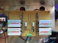
These two pictures are the B side of the DAC and a detail of the battery board. One board serves two SEN, with 18 V or 27 V with two or three 9V batteries. The output goes with wires to the DAC board, without binding post. I ended up soldering the batteries to the contacts for better stability.
You can see two pairs of binding post. The one with the resistors goes to the connector for the Laptop PSU that works as charger. The value of resistor has been selected following EUVL trickle charger posted in this thread.
Basically when the DAC is off the relays are not powered the battery packs are paralleled and connected to the charger. When I switch on the DAC the relays are powered, so the batteries are disconnected from the charger and connected to the I/V. The relays are controlled by the second pair of contacts. On board there is a 7805 regulator, so basically I can feed whatever to control the relays. What's still pending is a system to monitor the charge level of the batteries. From experience it will take a while to realize that the batteries are too low, mostly if you listen continuously.
It's also true that it never happened to me to flatten the batteries in a single session, but it's nice to have indication that you forgot to charge it, or that a cell has a problem. I used a simple circuit (also posted some time ago here) and it does the job. I will probably add it to the board. I was trying to think the best way to arrange it, in a way not to create an antenna to pick all the possible noise around.
Let me know if you need more info. I think that the 18.5V cells for model cars or drones would be easier to implement, but they cost something like 50 euros a pack. So I'll use as ultimate solution.
D.
Attachments
Preparing things for the ESS9018 SEN.
I decided to go with a touch screen. The display is from 4dsystems and can control the DAC without extra components( no arduino). A lot of coding behind this, but almost finish. I plan to report on the display the battery status.
I have few options to go:
1) check the status of the batteries continuously and use an optocoupler to leave the batteries floating.
2) check the batteries status on demand, connecting the temporary with a relays.
I also have option to report a yes no state, without adding an extra arduino or report a level using the advice of an extra arduino.
The easiest way would be to do it continuously with the yes no logic, but I am not sure if this would affect the sound. Any other component type I could use to connect the batteries to report the status?
Davide
Preparing things for the ESS9018 SEN.
I decided to go with a touch screen. The display is from 4dsystems and can control the DAC without extra components( no arduino). A lot of coding behind this, but almost finish.
Davide
Wow! I'm blown away!
 Uh, would you be sharing your code for it?
 Also, is this the part you're using?
Mouser Part #: 971-UOLED-160-G2
Manufacturer Part #: uOLED-160-G2
Manufacturer:4D Systems
The display is a uLCD-43-PT. It's not very new, but I think any of the 4.3'' display from 4dsystem would do. For compatibility it's better if it is Picaso, but I don't think it's a big deal if it's the new diablo. This unit has a I2C port and enough digital i/o to control power switch, mute switch (if you want one) and acquire the status (good or bad) of four batteris. The only thing I did not figure out yet is how to implement a remote control. If I add a small arduino I know how to do, but I am sure there is a smarter way to do that.
If you take the display it's better to get the PCT, that has capacitive touch, mine is resistive, but it works fine, buttons are big. I got the display from Sparkfun. You can get from 4Dsystem, but the shipment is a killer.
One thing I wanted to add it's a SE configuration that flip the phase of the negative pole, so if you want to use the DAC in SE without a converter, you can just make a cable that connect the two phases and have the double of DACs. You will not get any noise cancellation, but it's better than a kick in the face.
Out of curiosity, this has been an "on the road project". Yesterday I started coding in the hotel room, when I look at the time it was almost morning. Fortunately in the part of the world I am, it's WE.
If there is interest, I have no problem in sharing the code and in case we should move the discussion in a separate thread.
D.
Actually Mouser has the display on stock: uLCD-43PT-Pi 4D Systems | Mouser
- Home
- Source & Line
- Digital Line Level
- Zen -> Cen -> Sen, evolution of a minimalistic IV Converter