I'm not sure what you mean Pano - just terminate the RG59 cable with a 30ohm to 50ohm resistor (typical RCA impedance, I think) instead of the 72R as SY has used in his test set-up & test again!
Here's the way I see the test configuration, maybe SY can confirm that he has it set-up in this way:
Hiface ->BNC connector ->RG59 cable ->BNC connector ->BNC T ->Termination (50 ohm)
Scope is connected to third leg of BNC T
Then add in attenuators:
Hiface ->BNC attenuator(6dB) ->BNC connector ->RG59 cable -> BNC connector ->BNC attenuator (10dB) -> BNC T ->Termination (50 ohm)
Last edited:
But I don't know SY's test set-up because he has not spelled it out - it's obviously different to above as he has soldered in a 72R but where?
No, I did not use a 50R termination. I used 72R and 110R. I was interested in the latter because that's the termination resistance of the DCX. The M-Audio and Echo terminate in 75R nominal.
OK, thanks for the signal flow.
The problem I see is that RG59 and BNC are good. You aren't going to get the reflections that RCA or other bad connectors give you. And I don't think that simply terminating the good BNC with 50 ohms will do that.*
So I believe that you would want RCA connectors at each end. If you need a T in the middle for measurements, then it could be inserted. 2 RCA to BNC cables with a T between them should work fine. Another T can be added to that for the attenuators, if needed.
* Back about 15 years ago there were a lot of 50 ohm BNC connectors and terminators floating around the pro video world. They had come from the old Token ring coax network cables. They were cheap. They worked OK, but were not ideal. Don't see them much any more. (spdif is very similar in BW and level to a composite video signal)
Thinking about it, I suspect Sy's termination is done before the T connection to the scope, not after & I suspect that is why his plot is different to the others posted here. As far as I know the test configuration I set out is the one used by Joseph K & Mike Galusha (the two sources of these plots) & is the one I used.
Pano, AFAIK, the test set-up I laid out will work as is shown in the scope shots already published.
Sy did you use this set-up or can you say what you used please? I've asked this a number of times, now!
Pano, AFAIK, the test set-up I laid out will work as is shown in the scope shots already published.
Sy did you use this set-up or can you say what you used please? I've asked this a number of times, now!
Last edited:
There's no T connection- that's a likely path to error. At these frequencies, a high quality 10x probe (you apparently didn't read that part) right at the termination is the best way to measure.
Termination means termination. Is that a difficult concept?
Termination means termination. Is that a difficult concept?
Ok, no I didn't see that - I'll leave others to debate this.There's no T connection- that's a likely path to error. At these frequencies, a high quality 10x probe (you apparently didn't read that part) right at the termination is the best way to measure.
Termination means termination. Is that a difficult concept?
No, it's not but is it too much to ask for a measure of a mis-terminated line as it's the reflections & their possible reduction that we want to try ascertain!
OK, fair enough. Once you get the FFT for jitter going, we may be able to see the results of adding attenuation to a bad cable/connection.
(spdif is very similar in BW and level to a composite video signal)
Not so - spdif's level is certainly similar but its bandwidth tends to be quite a lot wider than a composite video signal (which is typically around 6MHz, assuming its not HD).
Take the scope shots we've seen - I recall Joseph K mentioning a rise time for the spdif output of the Hiface at 1.8nS. This corresponds to a (gaussian) bandwidth of around 200MHz. Of course it can be bandlimited at the expense of greater jitter - to bandlimit to 6MHz though would give a rise time of 58nS.
The upshot is - spdif is typically far more sensitive to termination than a composite video signal.
Oh yes, and I should mention that the Chinese unit was measured with only RCA, no BNC.
Ok & the Chinese unit shows no appreciable reflections - correct? I imagined that it should do with an RCA connector, hmmm! If your testing regime is valid then you are indeed showing us something new.
Maybe George or Thorsten will look in & have some comments about the test methodology?
Last edited:
Yes you measured the characteristic impedance (how did you do this, btw?) & terminate properly, well done! Now why not do the test that was intended - to prove if these attenuators reduce reflections which probably occur in a lot of implementations (certainly ones that haven't been carefully measured & setup to avoid reflections)
TDR
I will just refer back to post 45 in which George outlines his test set-up:
And here's the scope shot from that post
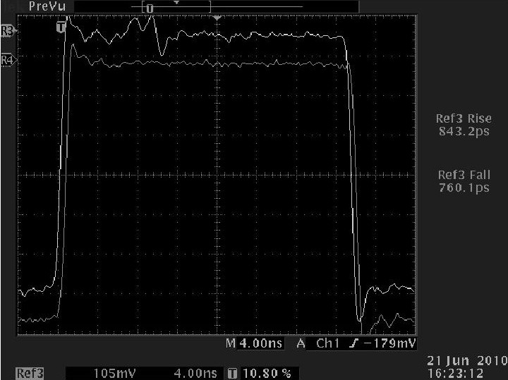
Here it is the difference before / after the insertion of an attenuator into a deliberately "wrongly" terminated 75ohm transmission line.
the setup is:
Upper trace
generator - 75ohm line - BNC tee (real 75ohm) - 75ohm termination.
The BNC tee goes into the 1Mohm input of my scope.
Lower trace
generator - 75ohm line - 10dB 75ohm attenuator-BNC tee - 75ohm termination
The BNC tee goes into the 1Mohm input of my scope
As you see, the only diffeence is the attenuator. The traces are normalized, so as to see the same percentage of the reflections.
I did not put up here the Hiface driver, because:
-I do not intend to discuss about it's output waveform
-I've put it on Diyhifi.org, please go and see.
The driver used is a 250MHz Hp pulse generator. The rise & fall times, ~700psec are limited by the scope.
The Hiface is only slightly worse, 1.8nsec rise time.
Last but maybe most important note: I show this setup & graphs again and again, because EXACTLY THIS IS the difference what your dac sees on it's input.
And here's the scope shot from that post
Not so - spdif's level is certainly similar but its bandwidth tends to be quite a lot wider than a composite video signal (which is typically around 6MHz, assuming its not HD).
Yeah, could be. I've never found a spec that tells me how much bandwidth a spdif signal actually needs. There must be some info somewhere, but I haven't seen it.
I run a lot of HD signals over coax/BNC as well. They certainly are sensitive to bad terminations and bad cables. But it's not hard to get it right. I don't think spdif is any more sensitive than HD video. Is it?
I don't think spdif is any more sensitive than HD video. Is it?
My experience playing with video signals predates the existence of HD, so I haven't a clue. 🙂 HD video is analog though - so in one sense it is more sensitive to reflections, because those become visible ghosting. Spdif being digital has its data fairly insensitive to reflections, but its jitter isn't. I guess HD video has at least 3 times the BW of vanilla PAL/NTSC so they could be quite similar in bandwidth terms in practice.
My estimate for the minimum BW of spdif would be 3X the basic data rate, which takes us to 18MHz. But this will come at the expense of fairly high levels of jitter. Hawksford has a paper relating jitter to bandwidth which I could find if you want.
Last edited:
BTW, before anybody else says it, if my premise about reflections & how these attenuators work was wrong & shown here to be false, I'll be the first to admit it.
They do still improve the sound but it will be another days work to find out how 🙂
They do still improve the sound but it will be another days work to find out how 🙂
I will just refer back to post 45 in which George outlines his test set-up:[/IMG]
Very cool! Thanks for re-posting. That's a dramatic difference.
What I don't know is what "a deliberately "wrongly" terminated 75ohm transmission line" is. He does not specify.
Whats the frequency of that square wave? About 16MHz, or am I reading that wrong?
...A singe tone makes it very easy to see. Have a look at the signal below. It should be a single peak at 1Khz. The extra spikes are because of the jitter.
Huh? Extra spices because of jitter. This is the analog output, right?
So the extra spikes to me are distortion. Of your device under test, of from your measurement equipment (input signal too high level).
😕😕😕
My laptop with either the Chinese USB->spdif straight in or the modified Hiface USB->spdif with both attenuators, run into DCX2496 digital input. DCX analog output run to M-Audio PCI card in my lab computer for FFT. No jitter sidebands seen from any of the sources. 64k data points, 96k sample rate.
The 4th, 6th, and 8th harmonics seem to vary from measurement to measurement (even with the same device), but were always below -110dB, often buried under the baseline. These appear to be analog distortion, but are low enough that I'm not going to spend time tracking them down.
So whether or not there's a difference in the spdif jitter, there doesn't seem to be any at the DCX DAC. And the horrors of the DCX don't seem to be evident- the baseline is hugely better than what one needs to see jitter effects if indeed they were there- they're not. This is with the gain settings somewhat compromised to prevent overload of the M-Audio card- even with that, the resolution, distortion, and noise are far better than any established threshold. FAR better.
Attachments

If it was distortion caused by device nonlinearity or clipping/compression, you'd see it in the form of harmonics of the original tone. Not as spurious tones, especially not tones at a lower frequency than the source tone.Huh? Extra spices because of jitter. This is the analog output, right?
So the extra spikes to me are distortion. Of your device under test, of from your measurement equipment (input signal too high level).
😕😕😕
Putting jitter on a sine wave effectively causes phase modulation of that sine wave. And if the jitter has strong frequency components, you'll get bessel spurs. They'll show up at Ftone +- Fjitter, Ftone +- (2*Fjitter), etc. Which is pretty much what you see in his plot.
If you adjust the amount of jitter on the interface (eg, by replacing the termination resistor in the receiving end with a pot, and tweaking the amount of mismatch) and the level of the spurs goes up and down, that will prove the jitter theory. Panomaniac, give it a try if you've still got the equipment set up.
- Status
- Not open for further replies.
- Home
- Source & Line
- Digital Source
- RF Attenuators = Jitter Reducers