Bulding a preregulated +- 10V for analog stage to be finally regulated to +-5V.
I'm looking for a very clean preregulated supply so I set to build a CRCLC-Reg-C.
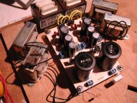
In order is 4700u film bypassed, 10 Ohms, 2200u, 1.3H, 2200u LM317T/337T and 4700u. The adj terminal of the reg y bypassed with a 10u lytic and a .47u film cap.
The final regs will be a simillar to LM431 at the analog pins of the chips.
The problem is that I can't have a completly clean line at the scope when using it wide open (200 Mhz). When a low pass filter is applied up to 20KHz the line appears clean. When wide open the line is thicker at 5/10 mv scale (using a 10X probe)
I have tested different transformers, bypassing and up to 4 inductors but still the line is thicker.
Am I dreaming to have a clean supply to the MHz?
I'm looking for a very clean preregulated supply so I set to build a CRCLC-Reg-C.
In order is 4700u film bypassed, 10 Ohms, 2200u, 1.3H, 2200u LM317T/337T and 4700u. The adj terminal of the reg y bypassed with a 10u lytic and a .47u film cap.
The final regs will be a simillar to LM431 at the analog pins of the chips.
The problem is that I can't have a completly clean line at the scope when using it wide open (200 Mhz). When a low pass filter is applied up to 20KHz the line appears clean. When wide open the line is thicker at 5/10 mv scale (using a 10X probe)
I have tested different transformers, bypassing and up to 4 inductors but still the line is thicker.
Am I dreaming to have a clean supply to the MHz?
Attachments
Your probably dreaming if you think your scope has that kind of sensitivity. I always use my scope with the 20MHz low-pass engaged if I have the vertical set below 20mV/division. The scope just has too much noise, and the high-impendance probes pick up stray emissions from everywhere.
If you really want to measure below 20mV/div, use coax and the 50Ω input termination instead of a regular 10X probe.
If you really want to measure below 20mV/div, use coax and the 50Ω input termination instead of a regular 10X probe.
I agree. You are measuring the noise on the exposed wires and the probe, as much as noise in the power supply. If you have to use a 10x probe, put something like a 40-100uH hash choke in series with the probe. Also, engaging the BW limit and or the inline choke on your scope will let you see any remaining 120Hz ripple w/o the HF noise.
")
apassgear said:In order is 4700u film bypassed, 10 Ohms, 2200u, 1.3H, 2200u LM317T/337T and 4700u. The adj terminal of the reg y bypassed with a 10u lytic and a .47u film cap. *SNIP*
Am I dreaming to have a clean supply to the MHz?
You will find the supply to be "cleaner" without the LM317/337 regulators, or if you have to use them to get the noise down to the microvolt level you need a quieter error amplifier and voltage reference than the one resident in these devices. The Jung and Sulzer setups have been discussed frequently on this site.
wrt measurement -- you can directly solder a piece of coax to the terminus at the power supply and a BNC connector on the other end. also check the scope AND power supply to see that they are both plugged into the same outlet !
Re: Re: 5V PSU question for Aanalog
Actually I have a Jung +-15V reg installed on the CDP for the analog section but my gut feeling tells me that they don't sound very good. Though I have to confess that the OpAmp on these are NE5534. With this setup they produced a lot of oscillations when trying to set up a LM6181 I/V analog stage with the TDA1541A S1 DAC.
For this reason I wanted to try the described supply which seems an overkill as a preregulator. I added the LM317/337 just to get rid of the voltage fluctuation of the mains line and have the final shunt regs, LM431 type, have an easier job at the now beeing construted OPA660 I/V buffer.
I don't care about the size or cost of this pre reg, up to a point of course but want a clean output and that's why is taking so long on the contruction and "testing".
At this moment I'm using only one inductor (1.3H, 33 DCR) at each rail between two 2200u caps. The other two were intended for use at the ground side. Using them at that position they seem to worsen the noise using my crapy test setup.
Is ther a better way of using the spare inductors, say in place of the 10 Ohms resistors to form a CLCLC before the regs?
Which would be a better way to get rid of the mains voltage fluctuation?
Thanks for the input!!!
jackinnj said:
You will find the supply to be "cleaner" without the LM317/337 regulators, or if you have to use them to get the noise down to the microvolt level you need a quieter error amplifier and voltage reference than the one resident in these devices. The Jung and Sulzer setups have been discussed frequently on this site.
Actually I have a Jung +-15V reg installed on the CDP for the analog section but my gut feeling tells me that they don't sound very good. Though I have to confess that the OpAmp on these are NE5534. With this setup they produced a lot of oscillations when trying to set up a LM6181 I/V analog stage with the TDA1541A S1 DAC.
For this reason I wanted to try the described supply which seems an overkill as a preregulator. I added the LM317/337 just to get rid of the voltage fluctuation of the mains line and have the final shunt regs, LM431 type, have an easier job at the now beeing construted OPA660 I/V buffer.
I don't care about the size or cost of this pre reg, up to a point of course but want a clean output and that's why is taking so long on the contruction and "testing".
At this moment I'm using only one inductor (1.3H, 33 DCR) at each rail between two 2200u caps. The other two were intended for use at the ground side. Using them at that position they seem to worsen the noise using my crapy test setup.
Is ther a better way of using the spare inductors, say in place of the 10 Ohms resistors to form a CLCLC before the regs?
Which would be a better way to get rid of the mains voltage fluctuation?
Thanks for the input!!!
apassgear said:Bulding a preregulated +- 10V for analog stage to be finally regulated to +-5V.
---------------------------------------------
Why not use a 6V battery; an 18VA one lasts forever!
If by mains fluctuation you mean ripple, I don't see how there could be enough left after two stages of regulation to affect the output. Not so you can easily say the output stage does not sound good. The ripple and any line variation should be a fraction of 1mV after the first 317/337 stage, and if your Jung regulator works at all the way it is supposed to, down to less than 100uV at the output stage. (btw, you said +/-10V in your first post, and +/-15 in the last one).
I would look elsewhere, but just to make sure the power supply is not the cause, how about replacing it with two 9V batteries temporarily, only at the output stage? Meaning take the regs out of the loop and see what it sounds like. If you decide to try that, leave any local decoupling in place though.
PM
Maybe he just doesn't like the sound of the Jung regulators? Some people on this forum have complained that the superregualtors are not to their liking.
Could be the same effect regarding why people like tube distortion. Perhaps the Jung regulator is so good that it exposes a flaw somewhere else in the circuit.
Could be the same effect regarding why people like tube distortion. Perhaps the Jung regulator is so good that it exposes a flaw somewhere else in the circuit.
Maybe also compare the local decoupling at the DAC and the NE5534 op amp with some of the other TDA1541A designs described elsewhere on this forum.
The NE5534 data sheet lists a power supply rejection ratio of 80-100db, so if all else is OK, even with, say 1mV of noise on the supply, another four+ orders of magnitude reduction would be less than .1uV on the output. The power supply effects should be less than the equivalent input noise or harmonic distortion introduced by the op amp. Assuming decent decoupling and good grounds, separation of the digital and analog supplies using ferrite beads, etc.
Is this a true A-B listening test? w. headphones or something else?
Thanks for all the replies, I'm learning a lot.
Hope didn't cause confusion, my previous I/V + analog was +-15V worked with the Jung regs and this regs use an NE5534 Op Amp (error correction) to drive the output stage.
The new stage is based on Thorsten proposal for the use of OPA660 as a I/V buffer stage. But since this Op Amp need +- 5V I decided to redo the PSU instead of lowering the voltage of the Jung regs, and since I'll be using a shunt regs at the pins of new stage Op Amp I could even have left them as they are but decided otherwise.
What's the penalty of using the 5534 as error Op Amp on the Jung regs?
Can the Jung regs be used for feeding the DAC on its +-15V pins?
Bricolo said:I can't understand why people use CLC or CRC filters for other things than class A
My idea of using CRCLC filter before the reg is the atempt to get rid of the RF generated at the diode bridge. Dose not work?
jwb said:Maybe he just doesn't like the sound of the Jung regulators? Some people on this forum have complained that the superregualtors are not to their liking.
Could be the same effect regarding why people like tube distortion. Perhaps the Jung regulator is so good that it exposes a flaw somewhere else in the circuit.
Frankly I don't have much experiance comparing regulators. Most likely my previous I/V stage was the culprit and not the regs, this I/V was based on Jung's proposal on the Pooge series using a CFB Op Amp.
Re: Re: 5V PSU question for Aanalog
fmak said:apassgear said:
Why not use a 6V battery; an 18VA one lasts forever!
PMiczek said:
I would look elsewhere, but just to make sure the power supply is not the cause, how about replacing it with two 9V batteries temporarily, only at the output stage? Meaning take the regs out of the loop and see what it sounds like. If you decide to try that, leave any local decoupling in place though.
PM
Very good idea to compare with batteries, that's something I'll be looking forward of doing.
But since I will have the shunt regs at the pins they may consume to much current, don't know.
apassgear said:
My idea of using CRCLC filter before the reg is the atempt to get rid of the RF generated at the diode bridge. Dose not work?
I think that snubbers are specially made for this
Bricolo said:
I think that snubbers are specially made for this
There was a huge thread regarding this topic and still I feel that the last word has not been said regarding the effectiveness of snubbers.
The question would be now if the choke dosen't help to clean the RF garbage.
I don't see how there can really be a question about it. If you diodes are producing high-frequency transients when they cut off, a correctly tuned snubber will keep the transient off the line.
Maybe the question is whether or not the transients are produced in the first place, but you seem to be operating under that assumption.
Maybe the question is whether or not the transients are produced in the first place, but you seem to be operating under that assumption.
- Status
- This old topic is closed. If you want to reopen this topic, contact a moderator using the "Report Post" button.
- Home
- Source & Line
- Digital Source
- 5V PSU question for Aanalog