Beats me, but that wasn't the terminal I was referring to. A three terminal regulator lacks the important SENSE lead.
Are we still discussing the first stage of regulation in the power supply, before the second "local" stage of regs?
Yes 140dB is questionable, but the point (for me) of doing my own audio is to make something that isn't provided by the market, do it better than the market, or do it as well as the market but for less money. If I only aimed for 96dB S/N I might as well buy a discman and call it a day.
Agreed, but not everyone is aiming that high, or has the resources to lay out, fab and test essentially perfect circuit boards.
Even at 120db most people will not be able to build, let alone test a circuit which has to resolve signals in the 5-10 microvolt range in the presence of other 3 and 5 volt digital signals.
I think that it is important to relate the circuit performance to the audio signal and source material in some way. I started with trying to answer a question about why we care about noise which is well out of the audio band at the output of a 50-cent first stage regulator (chuckle).
PM
PMiczek said:Power supplies are often at first neglected in D/A and A/D designs, and later often blamed for problems they have nothing to do with.
My experience with Jung-type regulators is limited, and if I were given a choice on which circuit I could make work better in a do-it-yourself context, I would pick a 3-pin or 5-pin integrated regulator supply, along with a local regulator, pretty much as described at the beginning of this thread, and without the oversized filter inductors. (well, I DID try to make a case for oversized heatsinks earlier...)
Excellent orientation, this was the information I was looking for and it came in spades!!!
My electronic knowledge is quite limited but I do understand most of your explanation and it makes a lot of sence at the DIY level.
Thanks!!!
Re: jung superregs
Thanks for your input and Andy's link, seems super-regs can only be done by experts, would like to try one of those but mostly I'm interested on DIY stuff even if that means I cannot attain the highest level
ced said:Hi passgear,
if I can just drop my pennys worth in, you really owe it to yourself to try the jung superregs as produced by Andy Weekes. He has a website at http://www.alw.audio.dsl.pipex.com/ with heaps of information even if you decide not to buy. I've tried lm337/317 and the lt1086 regs with full decoupling, in dual, single, dual tracking modes, sulzer regs etc with all manner of psu combinations and frankly the audible differences were negligible in comparison. His regs dump all over the competition from a huge height and you can hear the differences from the first 2 notes.
Thanks for your input and Andy's link, seems super-regs can only be done by experts, would like to try one of those but mostly I'm interested on DIY stuff even if that means I cannot attain the highest level
ALW superregs
Hi passgear,
he actually sells them as kits as well so you still have to put the suckers together. If you ask him I'm sure he'd be ok about you etching your own pcbs or maybe he'd sell you just the pcbs. Have a look or download his manual http://www.alw.audio.dsl.pipex.com/Manuals/ALWSR_rev2.9_Iss004.pdf as it gives you the schematic and the components to use. I'm sure he'd be ok about you etching your own pcbs if you ask him. He seems a seriously nice guy and not in it for the money.
I'm really not joking though. I would never waste my time with any other regulator now; the differences between the 3 terminal types and configurations are frankly negligible and you can tinker for years going ... oh, the bass is a bit firmer this way. I think. Is that a bit more instrumental seperation? It must be. witter witter. If you are going down that route, just bung in a lm317, decouple the adjust pin with a 10uf tant and have done with it. Don't waste your time worrying about regulation any more than that as the sonic differences at the end of the day really are minute- for the results its just not worth the effort of experimenting(again IMO).
BUT... if you want to REALLY hear what power regulation can do please do try these. Just try one. You will not regret it. These ARE worth time and effort.
Jeeze I sound like an ad. Anyway, enough.
cheers and good luck
Ced
Ced,
I had a look at Andy's site the first time you posted it, very interesting, but they don't show prices of the kit. I did send a message though. He is all the way up on UK so I'm concern about delivery cost, I'll check on that, maybe we could arrange airmail.
I may do this just for comparison purposes.
The other alternative posted by PM, Per Anders (DIYaudio member), also looks good. There seems to be quite a number out there.
Bricolo said:apassgear, can you post the shematic of the regulator you want to use (the circuit after the clclc+lm117)
what about this regulator, taken from national's lm117 datasheet?
Bricolo,
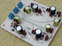
Instead of posting the schematic, that I have not prepared, let me show a pic of what's going on beyond the pre regs.
Most of the parts on top of the board are the 4 regulators (+-5V) one each polarity for each OPA660 (SOIC) which will be mounted on the copper side of the boards.
You can see on the first plane corner the regulator plus all the caps and resistors requiered.
A short explanation of each regulator is a 1000u filter (gold colored) bypassed with a film .47u next is a 100 Ohms series resistor that feeds the regulator, two resistors forming a voltage divider for setting the reg voltage. Next is a ferrite bead on a jumper that feeds the decoupling caps first one lytic 220u 50V Panasonic FC (dark blue one) next 10nf and 470pf both polypropylene. And once again, if you have missed that part the regs are LT431 well known on this forum.
Have not mounted the OPA's since I´m checking the regulators with a resistive load for some 15 mA.
Found out that 3 of the 4 regs were out of spec. some noise at arround 50KHz, but these parts were from NTE (NTE999) which are relacement parts supposly good ones. But most surely are scrap from the manufactures and rebranded out of spec parts (after this experiance.
But the good news is that I got some genuine TI parts (LT431) this afternoon. A real surprise to get these parts on this town. I was lucky.
If you realy need the schematic let me know.
On your posted schematic I have no idea. May be some other member can make some coments.
Attachments
AFAIK, the 431 is a precision voltage referenceapassgear said:
Bricolo,
Instead of posting the schematic, that I have not prepared, let me show a pic of what's going on beyond the pre regs.
Most of the parts on top of the board are the 4 regulators (+-5V) one each polarity for each OPA660 (SOIC) which will be mounted on the copper side of the boards.
You can see on the first plane corner the regulator plus all the caps and resistors requiered.
A short explanation of each regulator is a 1000u filter (gold colored) bypassed with a film .47u next is a 100 Ohms series resistor that feeds the regulator, two resistors forming a voltage divider for setting the reg voltage. Next is a ferrite bead on a jumper that feeds the decoupling caps first one lytic 220u 50V Panasonic FC (dark blue one) next 10nf and 470pf both polypropylene. And once again, if you have missed that part the regs are LT431 well known on this forum.
Have not mounted the OPA's since I´m checking the regulators with a resistive load for some 15 mA.
Found out that 3 of the 4 regs were out of spec. some noise at arround 50KHz, but these parts were from NTE (NTE999) which are relacement parts supposly good ones. But most surely are scrap from the manufactures and rebranded out of spec parts (after this experiance.
But the good news is that I got some genuine TI parts (LT431) this afternoon. A real surprise to get these parts on this town. I was lucky.
If you realy need the schematic let me know.
On your posted schematic I have no idea. May be some other member can make some coments.
what is the active regulation part in your circuit? I don't think a 431 can give enough power
Schematic
Hi Tony,
A posted schematic from you would be nice .
I have a hard time following you.
OPA660, TL431??
Current conveyer in a power supply regulator? Looks like a whole new approach to regulator design.
Labcenter has a free schematic capture program than can export schematics as a BMP-file. With the free Irfanview you can convert easely to GIF, TIF, JPG etc.
Irfanview can be downloaded at: www.irfanview.com
ISIS schematic capture from: http://www.labcenter.co.uk/shareware/index.html
apassgear said:
Bricolo,
Instead of posting the schematic, that I have not prepared, let me show a pic of what's going on beyond the pre regs.
Most of the parts on top of the board are the 4 regulators (+-5V) one each polarity for each OPA660 (SOIC) which will be mounted on the copper side of the boards.
You can see on the first plane corner the regulator plus all the caps and resistors requiered.
A short explanation of each regulator is a 1000u filter (gold colored) bypassed with a film .47u next is a 100 Ohms series resistor that feeds the regulator, two resistors forming a voltage divider for setting the reg voltage. Next is a ferrite bead on a jumper that feeds the decoupling caps first one lytic 220u 50V Panasonic FC (dark blue one) next 10nf and 470pf both polypropylene. And once again, if you have missed that part the regs are LT431 well known on this forum.
Have not mounted the OPA's since I´m checking the regulators with a resistive load for some 15 mA.
Found out that 3 of the 4 regs were out of spec. some noise at arround 50KHz, but these parts were from NTE (NTE999) which are relacement parts supposly good ones. But most surely are scrap from the manufactures and rebranded out of spec parts (after this experiance.
But the good news is that I got some genuine TI parts (LT431) this afternoon. A real surprise to get these parts on this town. I was lucky.
If you realy need the schematic let me know.
On your posted schematic I have no idea. May be some other member can make some coments.
Hi Tony,
A posted schematic from you would be nice .
I have a hard time following you.
OPA660, TL431??
Current conveyer in a power supply regulator? Looks like a whole new approach to regulator design.Labcenter has a free schematic capture program than can export schematics as a BMP-file. With the free Irfanview you can convert easely to GIF, TIF, JPG etc.
Irfanview can be downloaded at: www.irfanview.com
ISIS schematic capture from: http://www.labcenter.co.uk/shareware/index.html
Re: Schematic
Ooops, Am I doing somthing wrong?
Sorry guys for the delay, I was out of town for a couple of days.
I'll try to post a schematic Sunday.
But the good news, once again, is that the whole system is up and running beautifuly, but that needs a new thread to be as soon I can manage the last adjustments to center the OPA's response which is at the moment at +0.250V offset.
Elso Kwak said:
Hi Tony,
A posted schematic from you would be nice .
I have a hard time following you.
OPA660, TL431??
Ooops, Am I doing somthing wrong?
Sorry guys for the delay, I was out of town for a couple of days.
I'll try to post a schematic Sunday.
But the good news, once again, is that the whole system is up and running beautifuly, but that needs a new thread to be as soon I can manage the last adjustments to center the OPA's response which is at the moment at +0.250V offset.
- Status
- This old topic is closed. If you want to reopen this topic, contact a moderator using the "Report Post" button.
- Home
- Source & Line
- Digital Source
- 5V PSU question for Aanalog