jonners said:
I just want to report that I tried this method of connecting a separate 5V supply but couldn't get it to work. The disc would spin for a while but when it stopped the display showed zero and the disc wouldn't play.
An externally hosted image should be here but it was not working when we last tested it.
I've been looking at this and have some questions.
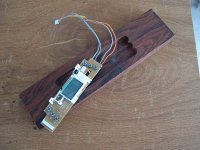
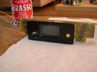
First we can see where L901 is removed to supply our 8vdc. To supply a separate 5v we have to remove Q902 and supply +5vdc to the opening left by the collector or to the + side of C916.
The negative sides of the +8 and +5 supplies would have to be reference (tied) together and be powered up at the same time?
I was wondering if we could tap into Peter's original supply just after the diodes and regulate down to a +5v supply from there?
An externally hosted image should be here but it was not working when we last tested it.
Regards,
Dan
dantwomey said:
I've been looking at this and have some questions.
First we can see where L901 is removed to supply our 8vdc. To supply a separate 5v we have to remove Q902 and supply +5vdc to the opening left by the collector or to the + side of C916.
The negative sides of the +8 and +5 supplies would have to be reference (tied) together and be powered up at the same time?
I was wondering if we could tap into Peter's original supply just after the diodes and regulate down to a +5v supply from there?
Regards,
Dan
Hello Dan
Yes, you can certainly tap the supply after the diodes to supply a 5V regulator.
The 8V and 5V supplies would then be sharing a common earth so you would only need one earth connection to the board.
However, as I said - I can't get this to work! This was, I believe, a suggestion that Peter made which he hadn't actually tried. The method he used was to cut the trace leading from the collector and connect the 5V there, but this looks difficult to me - I think the trace that needs to be cut is under the heatsink.
John
jonners said:
Hello Dan
Yes, you can certainly tap the supply after the diodes to supply a 5V regulator.
The 8V and 5V supplies would then be sharing a common earth so you would only need one earth connection to the board.
However, as I said - I can't get this to work! This was, I believe, a suggestion that Peter made which he hadn't actually tried. The method he used was to cut the trace leading from the collector and connect the 5V there, but this looks difficult to me - that trace that needs to be cut seems to disappear under the heatsink.
John
I'm missing why the trace would need to be cut. Couldn't we not use the collector pad from the removed Q902 as the location for the +5v wire? This leads to C916 which feeds the +5v to the require areas?
Regards,
Dan
dantwomey said:
I'm missing why the trace would need to be cut. Couldn't we not use the collector pad from the removed Q902 as the location for the +5v wire? This leads to C916 which feeds the +5v to the require areas?
Regards,
Dan
I believe Peter left Q902 in place, and cut the trace instead of removing it.
John
erik how did you aquire such industrial size pieces of copper, they seem so rare these days, the plate and tubing is of measurements beyond the normal end user market. your design seems to stear quite far away from your organelle mock up, where are you taking this design?
jonners said:
I believe Peter left Q902 in place, and cut the trace instead of removing it.
John
Yes. The jumper wire listed in playermods.pdf goes to the + side of C916. You could just cut the trace and feed your +5v there.
Regards,
Dan
dantwomey said:
Yes. The jumper wire listed in playermods.pdf goes to the + side of C916. You could just cut the trace and feed your +5v there.
Regards,
Dan
Yes, I think you're right Dan. But the schematic doesn't entirely agree with what's on the board. (Erik did refer to mistakes). The schematic shows the +side of C954 connecting only to the LA6541 chip. On the board it connects with the 5V+ at C916! (Mind you, I do have the EZ51 not the 31 - but all the component numbering etc. looks the same to me.)
John
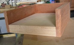
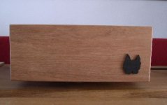
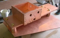
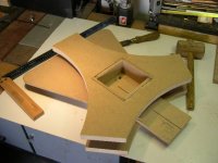
kanifee said:erik how did you aquire such industrial size pieces of copper, they seem so rare these days, the plate and tubing is of measurements beyond the normal end user market. your design seems to stear quite far away from your organelle mock up, where are you taking this design?
I was able to buy it (for the copper-price) from an industrial client .
I am still building according to my MDF scale...only the
bottomplate becomes a shallow compartment in real life...(such as in the Kalista...)
Since I never make drawings I build most of it "while I am at it"
I always give myself room for changes without loosing to much of my original idea.

Attachments
Hi all
I have just stripped down my first EZ31 and I am now starting to put together a component order.
Shigaclone PCB
1 x BG STD 1000/25v
1 x BG FK 2200/35v
2 x BG N 4.7/50 (I cant seem to find these anywhere, can someone suggest an alternative?)
1 x BG N 10/50v
1 x BG N 33/16v
1 x BG N 47/6.3v
1 x ERO 10n
1 x 300-8441 oscillator
PSU
2 x BG STD 1000/50v
2 x MSR860
1 x LM7808
1 x Dale 100R
1 x Dale 300R
I will use the standard transformer to begin with.
Chipamp (Dual Mono 3886)
For those of you who have tinkered with one of these, I thought I might upgrade the caps on this board with some blackgates. Which caps should I replace to achieve the greatest gain in audio performance? Panasonic FC are currently installed.
I am going to be ordering the parts from the US and want to try and get everything in one go so as to save on postage.
Is there anything I may have missed?
Thanks
Richard
@ Kanifee,
Wait just a while, there might be a powerbuy comming when this thingy doesn't work...")
http://www.boston.com/bigpicture/2008/08/the_large_hadron_collider.html
Wait just a while, there might be a powerbuy comming when this thingy doesn't work...
http://www.boston.com/bigpicture/2008/08/the_large_hadron_collider.html
Tripmaster said:
2 x BG N 4.7/50 (I cant seem to find these anywhere, can someone suggest an alternative?)
BG Std. or BG PK?

jonners said:
BG Std. or BG PK?
Hi Jonners
Duh!
I was looking at another supplier yesterday who didn't have them in std or pk but Percy Audio appear to have them on their price list. I will send them an email to find out if they have some in stock.
Have you tried any UK suppliers for Blackgate? I have looked at the hifi collective website
Is there anything else I may have missed?
Thanks
Richard
Tripmaster said:[B
Have you tried any UK suppliers for Blackgate? I have looked at the hifi collective website
Is there anything else I may have missed?
[/B]
Hi Richard
I got my caps from Parts Connexion. Filling in their order form was a bit tedious but delivery was extremely fast.
Don't think you've missed anything.
John
- Home
- Source & Line
- Digital Source
- Finally, an affordable CD Transport: the Shigaclone story