But seriously at some point, euphonics does play a part. Up to a certain point you can go and objective, then it starts to become system specific and euphoncally.
I can see you haven't heard DAC-3. It is objectively better and you would know it if you heard it. That's okay though. I hope you are enjoying the new DAC, that's the important thing right now.
Mark, have you compared the DAC3 to any other retail ESS dacs based on these newer chips? Like SMSL, Sabaj, Topping, Pro-ject, et al.?
There are some measurements and a review of DAC-3 at Stereophile. it is also on their recommended equipment list. The only new box I am aware of that the commercial mastering houses are starting to try instead in fair numbers is Crane Song Solaris. It uses a similar architecture in some ways to DAC-3, such as upsampling to 211kHz and offloading interpolation/reconstruction filter tasks to external Sharc chips, only it uses AK dac chips instead of sabre. That being said, DAC-3 is still very hard to beat. I doubt most of the players in the DAC business have the engineering chops to pull it off and the price would still have to be up around $2k for 2-channels given the hardware needed for doing all that stuff.
Benchmark DAC3 HGC D/A preamplifier-headphone amplifier Measurements | Stereophile.com
Last edited:
Moving ahead Today I encountered some problems and it took me an hour to figure out what the issue was.
Yesterday, Sunday evening, everything was working fine.
Today, I could not get the digital inputs to lock properly. No matter COAX or TOS. It would lock and then fall off and lose. On and Off On and Off.
I disconnected it and checked the voltages on the LT3042 module and the output was indeed 3.3V. Reconnected, and the same issue. Then I took out my old DAC and it would reliably lock on. So something was up.
Well in the end I found out something. Those transformers that are coupled with the DACs do not have the specs that they tout on the labels not close. I had adjusted the preregs to be 3V above the LT3042 output but it turns out that the prereg was not getting sufficient voltage and it has occasionally hanging too low and this caused the LT3042 to cut out momentarily. (The main culprit was that my line voltage was higher on Sunday as opposed to a weekday. Where it went over the edge in ok.)
I had thought that I would use one of those in the interest of saving space. In any case, it is going to come out. I put in a decent 10V AC source adjusted the preregs to there is a little more headroom and the heatsinks all share the dissipation. And yes, it appears that AVCC was better than before. In any case, it is now absolutely stable.
This weekend I am going to put on the spare 100VA toroid for the Analog IV section PS. That compact C core transformer will now need to be repurposed. Well a larger remote transformer box is forthcoming now. I will need to start looking.
Now let me discuss AVCC with the mods I performed. Today to test that the DAC was still good in diagnosing the problem, I was very fortunate that I was able to back up instantly and then reconnect the power to the LT1963s quickly. When I did so, I was able to listen again with the stock AVCC as well as test out that the DAC circuits were still good.
On this DAC board, the stock AVCC is much superior to the one on the 9038Q2M board I worked on before. When I was able to listen again, the errors on the sound was a slight muddiness as the music played and details were sometimes hidden that you could not pick out. I'll tell you in an analogous fashion.
Last week I had changed the front sway bar links in my auto. At only 100,000km, most mechanics would test them and say they are still good. No real odd sounds you could detect that would normally tell you to take it to the garage. Since I was getting some brake work done I elected to ask them to change them out. Why? They impart a tighter feel to the car motion and steering. What I did not expect was that it would make the car quieter. What? you won't see that in diagnosing these parts. But here is the reason...similar to the AVCC and low noise. When the end links wear, they have gaps in the joint. When the gap is really bad, then people report clunking on bumps etc. However before that time, when they wear, there is actually continuous small vibrations in the joint and since this gradual, we get used to it. When they are changed, suddenly you notice the car is quieter in an eerie way. A similar thing to the AVCC, when AVCC is not clean and stable, there the sounds that are supposed to make sense to our ears are suddenly not making sense anymore because they are distorted and while they might be there at the correct level, they become incoherent and it just sounds like the lower level details are all blurred out. When AVCC is good the DAC can output sound that is more coherent and makes sense to our brains. I am not an expert on this at all but this is what I now hear. It is hard to describe. Things now sound clear and COHERENT and the sounds all sound familiar and our brains are no longer confused as to what that sound is. The end result is clearer sound and surprising less listening fatigue. The sound as some will say sounds easy.....because everything is now easy to discern without effort to the brain.
This is what I heard again today. Before with the LT1963, the sounds and details are all there, BUT you needed to work at it and it can become tiresome after a while. Some sounds just sound odd to our brain. This is a comparison against the LT1963. With the 9038Q2M, the difference is even more dramatic. In comparison, the stock AVCC on the 9038Q2M is "bad" if I can say that?
So yes Sergelisses comment that the LT1963 does not sound bad is indeed correct IMO. But I think once he puts in a better AVCC, he will appreciate the difference. Is my AVCC better than an OP AMP one? I don't know. But it sounds darn good and I'm really enjoying it.
This evening I enjoyed Carole King's Tapestry album, the most ever in my life. I could hear the footwork on the piano pedals. Before I enjoyed the recording over the years but tonight her performance really connected. I could really appreciate the mixdown and production of I feel the earth move. The earth was now moving with my subs now in that song. I never realised that. It just sounded like noise before. What I always had considered a mediocre recording (1970?) (Sound wise) is now in a new light. The dynamics in her vocals revealed her energy at that point. It is now much more enjoyable.
Also, since the 80s, I was always searching for drum reproduction that kick your chest yet have the tightness and speed that real drums impart. It is all there now!! Well mostly as I need to upgrade my sub crossover PS asap.
If I were to do it again, I'd consider getting one of these.
Dual Way LT3042 Linear Regulator Power Supply Board DC Converter Pre-amplifier | eBay
It has two LT3042s on one board and you can install a 22uF Cset cap on each channel. AND you'd be able to rig up a 317 prereg or even LM7808 as a prereg once we remove the diodes. The source of the DC would be the RC circuit that the DAC board has built in for the LT1963s
You'd need to desolder both LT1963s from the DAC board. I'm not sure my soldering iron has enough heat to remove the tab solder. In which case, I'd cut the legs off the IC.
Also tonite, I realised that in December 2017 over the holidays I started looking for a cheap DAC $40. I never expected it would lead to what I have now. Be warned. You know MarkW4 is the culprit here.
Last edited:
So here is a list of stuff I used so far. As you know I prefer easy mods rather than elaborate mods. So I just get generic stuff off Ebay and repurpose it.
DAC ES9028 ES9028PRO DAC DSD Decoder board HIFI Audio + TCXO + remote control | eBay
LT3042 Low Noise LT3042 Linear Regulator Power Supply Board DC Converter Overvoltage | eBay
Or the one mentioned above
For the preregulator to the LT3042s, I used this but upgraded the caps.
LM317 Adjustable Power Supply Board With Rectified AC DC Input DIY Kit 699994708414 | eBay
I'd suggest getting a transformer with 15V+15V, 9V, 9V. Not the 15+15, 6,6 even if you use the RC circuit on the LT3042.
Separate stout transformers are preferred of course.
For the IV power supply, one safe way is to build this
Super Regulator – diyAudio Store
It is superior to the power supply I am using and your results might exceed what I got. Or you can use a favorite high performance PS.
The power supplies and regs should fit this custom case for the DAC especially if you got the dual LT3042 board. Transformers must be remote to allow space.
Aluminium DAC Chassis Enclosure Case for ES9038 DAC 280*62*211mm Silver/black fa | eBay
The transformers will need to be mounted remotely in a separate enclosure. I used an old surplusCorcom EMI filter to feed the transformers
Last edited:
So there. Not quite finished but an interesting journey the last 6 mos with Digital since 1998 or so. It is only because I started out with the 9038Q2M board and then found out along the way what needed to be done and then when I restarted, I mostly knew what I was looking for.
This has me wondering. If some designer fabs a board with the mods that was added and puts it all together, the cost could be a lot less than purchasing separate boards etc. The performance could be better as well.
No technology here is groundbreaking. So I really must wonder why not?
This has me wondering. If some designer fabs a board with the mods that was added and puts it all together, the cost could be a lot less than purchasing separate boards etc. The performance could be better as well.
No technology here is groundbreaking. So I really must wonder why not?
Last edited:
I have often asked myself the same thing, would be so nice to have cheap, and really nice dac.
I had one of the lt3042 boards, but it never produced anything more than 10ma or so, with a 5v input. Do they require more than that for 3.3v?
Absolutely for some reason. When I ran with a 8v it was fine. Then I thought I could run this board shown with a 3V headroom and it was touch and go for one and the other seemed to be OK. But I think my prereg was hanging. I have since run when I put in the higher voltage transformer at 8.5V and it now runs flawlessly. Not much heat either. I did not measure its stability on a scope or anything but tonite I just listened to Pat Metheny As Falls Witchita, So Falls Witchita Falls. Outstanding in presentation and POWER when it is called. If you know this cut, then you know when the current demands of your amps kick in and if your system does not have it, well it is pooped and sounds flat. When it has it, it just builds to scary levels. Details with all the percussion in the background and highlights was right there, especially if the lights are out.
Cheap and really nice normally are not associated. Even with this, time and effort costs something in the final outcome.
More to come with maybe better decoupling, shielded wire runs, cut flat sheets of copper foil for power supply runs, clocks and I will test an SRC. All my files are currently FLAC and MP3. On that note. I get better sound now with an MP3 and this DAC than I used to get with a FLAC and a poor DAC. A lot of the MP3 has to do with the quality of encoding so when people say MP3, it is not just the bitrate but the encoder used intially as well.
Last edited:
Yet another ultra low noise high PSRR LDO - LT3042
I have ordered 10 PCB in CHINA and yesterday i tested one .
Vin = 8v
180ma for the consumption . I put a litlle heatsink .
Vout =3.29v
R=4.7µf on CSet ( MURATA X7R)
I installed it ( in place of a DEXA 3.3v discrete regulator ) on a ES9028 DAC
I have no preregulation :Transformer =6AC ,rectifiers, capas 2x22000µf
First on the AVCC .....
I need time to have a good opinion
Serge
As Markw4 pointed out, you need to take a look at the graph on the data sheet on noise spectral density and when you increase the Cset to 22uF it falls dramatically as compared to the 4.7uF.
Page 10
http://www.analog.com/media/en/technical-documentation/data-sheets/3042fb.pdf
Noise Spectral Density: A New ADC Metric? | Analog Devices
This stuff is beyond my understanding.
Page 10
http://www.analog.com/media/en/technical-documentation/data-sheets/3042fb.pdf
Noise Spectral Density: A New ADC Metric? | Analog Devices
This stuff is beyond my understanding.
Last edited:
As Markw4 pointed out, you need to take a look at the graph on the data sheet on noise spectral density and when you increase the Cset to 22uF it falls dramatically as compared to the 4.7uF.
Page 10
http://www.analog.com/media/en/technical-documentation/data-sheets/3042fb.pdf
Noise Spectral Density: A New ADC Metric? | Analog Devices
This stuff is beyond my understanding.
I will try
I will also be purchasing a 22uF to replace the 47uF I used temporarily.
Remember to keep the leads as short as possible and possibly mount it right on the pins of the LT1963 which looks like is possible with the board you have.
I'm not quite finished because I need to put in some low noise leads and improve the ground lead to my LT3042 boards. Wires I know will not really be good enough. I plan in the end to put in sheets of insulated copper foil that must be custom cut and bent and will tie back my grounds and power leads. Inductance will kick in on these uber circuits so any trick you use is important as compared to the older analog. I need to also get some chemicals to clean off the flux around the LT3042. I keep reading the cautions in the app notes. It seems that to get the performance in the spec, you need to be really careful about implementation.
If you are putting power supplies outside of the board, read this
Simple Voltage Regulators Part 2: Output Impedance
and at the end, understand how your circuit is related to the output. This relates not just to three term regs but also to the LT3042 as well again at the performance levels of these devices every little connection and where counts.
I will be making some changes.
The above is important when we have systems where the grounding point of the first rectification stage is off the main board. If such is the case then it is better to make a separate ground channel from the main capacitor bank and take that directly to the main board or DAC. Your regulator that follows the two rails will then collect its grounds to a star point on the regulator board and tie back to the ground on the DAC or mainboard.
Now if you reuse the capacitors on the main DAC board to supply the raw dc to your outside regulator, then the situation is mostly taken care of provided the board layout of the offboard regulator was done properly. Again at these levels every single aspect of the design counts like crazy.
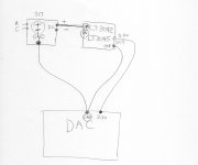
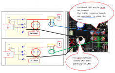
If you look at my pictures you will see that aspect. Notice that I do not use the adjustment leg at all to connect to my offboard regulator. I use a substantial ground point on the board the board designer has put in and I make a single low Z run to my star ground on my offboard regulator.
My connection to the AVCC is initally incorrect. What I need to do correct it since I am rectifying off board is to connect the ground point of the AVCC ground to the main ground point of my preregulator large cap. Connection to the LT3042 boards from the preregulator will only have one connection not two. Just the + voltage rail. The LT3042 main ground point will now lead back to the DAC board ground. In my case I think the negative pin of the cap on the LT1963 feed might be the best next best would be the large LT1963 tab. I will assume that the designer of the board out the traces of ground on board properly. In any case I have no control of that and must live with it.
Now when I remove or completely disable the LT1963. The situation is a lot less complicated because I would simply take the + voltage from the input pad to the LT1963, take that to the LT3042/5 reg and then the output to the output pad of the LT1963. There will be a single not so critical run to the LT3042 offboard. So if you can reuse the onboard raw power supply, it is much easier.
I imagine when you see designs with multiple regulators on the board, it means nothing unless you look at how the circuit traces are laid out and how they relate to allowing the regs to work. That is possibly what the author of the article is pointing out. So you can take a really good design, lay out the board incorrect and totally null out the design benefits. This is important because high performance audio requires low Z power supplies and despite all the designing and parts, a bad grounding scheme could totally make the effort to be nothing. This could be why some users report no differences between power supplies...it could be a bad grounding scheme swamping out the benefits.
Like I said, I got some work to do again myself.
Now if you reuse the capacitors on the main DAC board to supply the raw dc to your outside regulator, then the situation is mostly taken care of provided the board layout of the offboard regulator was done properly. Again at these levels every single aspect of the design counts like crazy.
If you look at my pictures you will see that aspect. Notice that I do not use the adjustment leg at all to connect to my offboard regulator. I use a substantial ground point on the board the board designer has put in and I make a single low Z run to my star ground on my offboard regulator.
My connection to the AVCC is initally incorrect. What I need to do correct it since I am rectifying off board is to connect the ground point of the AVCC ground to the main ground point of my preregulator large cap. Connection to the LT3042 boards from the preregulator will only have one connection not two. Just the + voltage rail. The LT3042 main ground point will now lead back to the DAC board ground. In my case I think the negative pin of the cap on the LT1963 feed might be the best next best would be the large LT1963 tab. I will assume that the designer of the board out the traces of ground on board properly. In any case I have no control of that and must live with it.
Now when I remove or completely disable the LT1963. The situation is a lot less complicated because I would simply take the + voltage from the input pad to the LT1963, take that to the LT3042/5 reg and then the output to the output pad of the LT1963. There will be a single not so critical run to the LT3042 offboard. So if you can reuse the onboard raw power supply, it is much easier.
I imagine when you see designs with multiple regulators on the board, it means nothing unless you look at how the circuit traces are laid out and how they relate to allowing the regs to work. That is possibly what the author of the article is pointing out. So you can take a really good design, lay out the board incorrect and totally null out the design benefits. This is important because high performance audio requires low Z power supplies and despite all the designing and parts, a bad grounding scheme could totally make the effort to be nothing. This could be why some users report no differences between power supplies...it could be a bad grounding scheme swamping out the benefits.
Like I said, I got some work to do again myself.
Last edited:
Why not connect the LT3042 ground back to the large cap ground that you removed? I think it better follows the advice in the article. The way it is now, it has impedance on the return leg on the decoupling cap point. Why remove the decoupling caps?
If you remove the first decoupling cap to AVCC, then one decoupling cap to the DAC is a short run......the other one on the other side of the DAC is a long run. Remember this DAC as it is now does not have separare L&R AVCC feeds. I think the first decoupling cap will help provide better separation between the L&R channels at high frequencies.
Personally I would use the output pad meant for the LT1963 to feed the 3.3V and put in a decoupling cap that was there initially. That way there is one more large decoupling cap to the DAC to each channel before it enters the DAC as the designers put it. Actually I might put in a tantalum just before the DAC like markw4 did on his other board.
Last edited:
Here is sketch for understanding
I am going to disagree a little. I would agree it would not be good to create a ground loop if possible. However, no ground loop is created if the ground for the LT3042 board runs through that board rather than around it. Otherwise, input ground current to the LT3042 board is running all over the place and potentially interacting with circuitry without any benefit. It may be good to recall that the main purpose of a star ground is to prevent any ground loops from forming. However, a ground plane is an alternate approach that allows for unlimited ground loops. Sometimes a ground plane can be a better choice than star ground. The trade-offs should be considered before blindly going one way or another.
In addition, I would say that the link you recently found about things that can go wrong with power supplies does describe some things that can happen, but is probably not such an issue in most cases. If proper caps are used with regulators and some distance, not much, separates that from various other bits of circuitry then there is already a little small resistance and inductance separating things enough so they probably do not interact especially pathologically.
If one wanted to see if there was a problem with a particular power supply, some current could be injected into the power supply output, say through a resistor connected to a signal generator. A LF square wave with maybe 10% or maybe a little more of the power normal supply current driving into the PS output should excite some anomalies if any are present. Or, alternatively, a swept sine wave could be used. If frequency peaking is seen as the frequency is varied then that would indicate there may be a problem. It would be particularly worrisome if the peak were tall and narrow indicating a high Q resonance. If some problem is found then it can be investigated and fixed. Obviously, when doing such experiments start with small excitations so as not to risk driving the PS output voltage into severe gyrations. We don't want to blow up anything.
Also, probably should mention there are more sophisticated methods for testing power supplies that may use techniques such as injecting a disturbance into the regulator control loop with a small transformer. A network analyzer can be used to measure the effects at different frequencies and then the loop may be compensated to correct for any potential regulation instabilities or variations outside of specified performance tolerance limits.
Last edited:
Well right now, I imagine I have it running all over because the ground from the 317 is going to the LT3042 and ground from there going to the DAC
Are you indicating that should we connect the input ground to the LT3042 to the ground on the 317, but NO connection from the output of the LT3042 to the DAC. It should be equally as good?
If so, which is good, better or bad? Can we sketch out with say similar sketch I made so I know what should be done. This presents a good opportunity for teaching in a practical sense.
I have no knowledge as yours so I need someone more knowledgeable about this.
Last edited:
I think it will depend on how things are located physically. I can't tell from a schematic alone. The way I do it myself is move parts, components, assemblies, etc., around so as to minimize potential problems with sensitive circuitry. For example, I would want the AVCC supply very close to the DAC pins, as ESS suggests. Once I figure that out, then I think about where voltage I need for AVCC supply input is located and look for a good spot nearby. Then I think about what currents are flowing where and about areas of any loops, particularly relative to things that make magnetic fields, like transformers, or circuits where high currents are flowing. I kind of do an EM field simulation in my head. In other words, it can be a bit of a puzzle with more than one possible solution. I can show you a picture of my current test layout. It may not be perfect, in fact it is not perfect in all respect but it works.
To think about a little more, for example, there may a ground loop somewhere because power wires go to two boards and some plug-in connectors also go between the boards. I can risk allowing a loop, or I could cut a power ground or the signal cable ground but unless I find there is a problem I probably won't worry about it too much and I will allow a loop to exist. So long as I keep the loop area reasonably small, there are no strong fields around nearby, and so forth, then I will try it. I could always run a test lifting a ground somewhere and break a loop to see if it affects performance. For analog that might mean checking for line frequency related spurs in an FFT. For digital it might mean looking at eye patterns or error rates, something like that.
Of course it also depends on what the circuit is for. If it might be used in other conditions then it should be designed and tested for conditions it should be tolerant of.
In other words I don't think there are simple rules of thumb that could be described on one web page that can give general answers for every case. I could recommend some good books to read, because it can be a complex subject.
Yet, a few words could be said about good practices. I think there are some good application notes around worth reading that summarize the most important things to think about reasonably well.
I like this one as an intro: http://www.analog.com/media/en/technical-documentation/application-notes/AN-202.pdf
And then maybe:
http://www.analog.com/media/en/tech...14948960492698455131755584673020828AN_345.pdf
http://www.analog.com/media/en/training-seminars/tutorials/MT-031.pdf
http://www.analog.com/media/en/tech...053265003392595605308453835483630769AN214.pdf
http://www.analog.com/media/en/training-seminars/tutorials/MT-095.pdf
- Status
- This old topic is closed. If you want to reopen this topic, contact a moderator using the "Report Post" button.
- Home
- Source & Line
- Digital Line Level
- Moving from 9038Q2M to a 9028Pro board