A simpler answer? We are talking about three circuit boards here and the interconnection between three of them. We are not in a position to remake any of the boards. So maybe a guideline as to how best to connect them as a starting point. you possess a sample of the LT3042 board. The 317 regulator is as basic as it gets and the DAC board maybe a little sketchy but you have pics and Sergelissed has some outline pics shown. So what is a good starting point to interconnect them?
In your case if you have a transformer, then a 317 pre-regulator, then an LT3042 final regulator to be used as an AVCC supply, I would wire them all up in series and only ground the last one, the LT3042 output ground very near where you connect output positive to AVCC pins. AVCC current will flow into the pins, some will go right through the dac chip and out the ground pad on its bottom, then return to the LT3042 board where you have connected its ground wire. Some other AVCC current will flow through the IV opamps then eventually back to your ground wire. ESS says to make the output stages on the same ground plane as the dac chip in a line-of-sight from the dac output pins. Hopefully the ground currents returning from there will have a straight shot back at least at higher frequencies through the power bypass caps on the IV opamps connecting right to the ground plane. LF components will have to work their way back through the +-15v power supply ground. So, keep it as close by as you reasonably can.
That's kind of how I would think of it without seeing it. When I got a chance I would look at it too and think about it some more. Eventually, I would settle on a layout to try.
That's kind of how I would think of it without seeing it. When I got a chance I would look at it too and think about it some more. Eventually, I would settle on a layout to try.
Last edited:
Thank You, As it turns out that is how I have it hooked up now. But when I look at the article it seems incorrect. Know what I will try it the alternate way and see if it sounds different.In your case if you have a transformer, then a 317 pre-regulator, then an LT3042 final regulator to be used as an AVCC supply, I would wire them all up in series and only ground the last one, the LT3042 output ground very near where you connect output positive to AVCC pins. AVCC current will flow into the pins, some will go right through the dac chip and out the ground pad on its bottom, then return to the LT3042 board where you have connected its ground wire. Some other AVCC current will flow through the IV opamps then eventually back to your ground wire. ESS says to make the output stages on the same ground plane as the dac chip in a line-of-sight from the dac output pins. Hopefully the ground currents returning from there will have a straight shot back at least at higher frequencies through the power bypass caps on the IV opamps connecting right to the ground plane. LF components will have to work their way back through the +-15v power supply ground. So, keep it as close by as you reasonably can.
That's kind of how I would think of it without seeing it. When I got a chance I would look at it too and think about it some more. Eventually, I would settle on a layout to try.
I'm a retired ME so I am looking at the circuits again and drawing what we call free body diagrams to understand what is going on. My conclusion theoretically is that the 317 should ideally be on the LT3042 board itself to ideally be similar to the article schema.
This will indeed hasten my removal of the LT1963s and utilize the onboard rectification on the DAC. I will modify the LT3042 modules to add local preregs on the entry of the module. I might even simply add a LM7808 (Don't have any of those) which would make it so simple..but I have a couple of LM317s, one that I removed from the DAC before. So I just need to calculate the dividing resistor.......which I can measure on the current prereg. OK thinking while I write. Simple. Done.
This will indeed hasten my removal of the LT1963s and utilize the onboard rectification on the DAC. I will modify the LT3042 modules to add local preregs on the entry of the module. I might even simply add a LM7808 (Don't have any of those) which would make it so simple..but I have a couple of LM317s, one that I removed from the DAC before. So I just need to calculate the dividing resistor.......which I can measure on the current prereg. OK thinking while I write. Simple. Done.
Last edited:
Looked at the circuit again last night and I have a solution and better understanding. In the prereg, what I will need to do is separate the 317 and forward ground from the main smoothing caps. The smoothing cap negative will go directly back to the main ground on the DAC board. and the 317 ground point will need to the attached to the LT3042 ground. The 3042 ground then connects back to the DAC board ground via another lead. note that there are two leads going back to the DAC board ground. The main smoothing cap is one cluster and one lead. The 317 regulator and followed by the LT3042 regulator now forms another cluster and the ground on this regulation cluster then ties back to the ground on the DAC. This then allows the 317 and 3042 a chance to best achieve its rated performance. I think I have it correct now. If anyone can see an error please let me know. I am NOT an expert and not really trained in electronics.
Very interesting.....and I now see why the author of the article, seemed a bit disappointed in what he observes being done. If he is correct, then indeed many outboard power supplies actually need two grounding leads to be correct. Ever see this? Is he right? I am in no position to say yes or no. But I will be trying it to see if it makes a difference.
Very interesting.....and I now see why the author of the article, seemed a bit disappointed in what he observes being done. If he is correct, then indeed many outboard power supplies actually need two grounding leads to be correct. Ever see this? Is he right? I am in no position to say yes or no. But I will be trying it to see if it makes a difference.
Last edited:
Also I note that there is an overlooked aspect. The regs can compensate for lead resistance of the ground wires. But looking at the article schematic, the lead resistance on the power side is assumed to be zero. So any lead resistance is added to the impedance of the regulator. So the power leads from the regulator needs to be low resistance...as low as practical.
Anyone comment if this is true?
Anyone comment if this is true?
Ever see this? Is he right?
Hard to visualize from your written descriptions things like layout on top and bottom, where traces run, where your outboard regulator is in relation to all that, and so forth. Hard to express an opinion without seeing it firsthand, or at least a schematic and photos that clearly show everything.
So the power leads from the regulator needs to be low resistance...as low as practical.
Anyone comment if this is true?
A regulator can compensate to some extent for upstream power quality/limitations. A regulator regulates the voltage where it's sense input connects to output/load. If the sense input is sort of internal to the regulator then only the voltage right at output pin of the regulator is being directly regulated.
Regarding output wires from the regulator to the load, probably good to twist them together, keep them as short as possible, and keep them thick enough to help minimize any voltage drop. But, voltage drop is not the only concern. Noise pickup in the output wires could also be an issue, which is why one would twist the wires together. Keeping the wires short helps to limit both voltage drop and noise pickup.
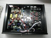
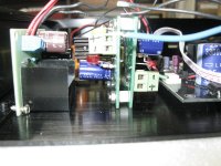
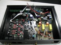
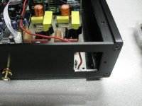
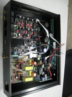
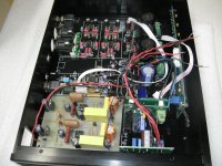
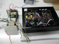
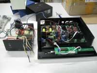
Dry fitting time to make sure that all the boards are physically able to fit and acquire what I will need for the final physical assembly. The wiring is still rough but when installed will be trimmed and new cables put it and routed and tied down. I will need to put in a filler plate over the IEC cutout and on this filler plate possibly put in one or two connectors to bring the AC in.
Attachments
Last edited:
Now comes the transformer or remote power case.
I am trying to reuse as much of what I have in my storage. Last run of projects.
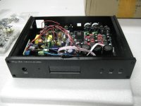
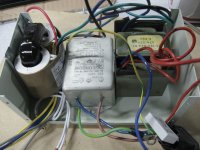
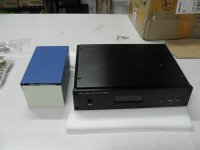
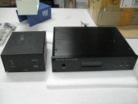
The first case, fit in the two transformers and the last one has some more space but will need some cleaning, spray paint and I will build an acrylic front panel and spray the rear black thus covering the holes already drilled out. Yeah, I could buy a new case that matches the DAC case. Still thinking about it and it could easily be redone in the future. The power is mostly tucked at the back that no one see anyways.
I am trying to reuse as much of what I have in my storage. Last run of projects.
The first case, fit in the two transformers and the last one has some more space but will need some cleaning, spray paint and I will build an acrylic front panel and spray the rear black thus covering the holes already drilled out. Yeah, I could buy a new case that matches the DAC case. Still thinking about it and it could easily be redone in the future. The power is mostly tucked at the back that no one see anyways.
Attachments
Last edited:
The final picture with the two black cases will likely be the look of the final DAC
That power case is repurposed from a THX EQ box I built in the 90s. Remember LaserDisc and VCR?
I'm looking for a sticker to place over that power hole. I have one I think will fit. It says AMD...which is what my PC is running.
At the end I will have something that will look entirely acceptable to my wife and visitors and myself.
Last edited:
The more things change the more they come back to the same?
Why would I say that. In the past period I took down the board and started to make
some changes. First I implemented or corrected the AVCC external power supply wiring scheme.
Next, I put in some high frequency decoupling into the op amp power rails as suggested by Markw4.
Next, I removed the silmic decouling caps nearest the DAC and installed some 47uF tantalums. For the first decoupling cap I installed a larger 470uF polymer SEPC caps that I had left over when modding the 9038q2m.
I also installed some 22uF tantalum caps as Cset on the LT3042 module.
Result was that the sound is again moved up a notch in refinement. Every single aspect to my ears satisfies at this stage. What do I hear. First, there is no untoward brightness at all. None, the sound is not sterile by any means yet it has a precise character. It sounds like very good vinyl except better than what I was getting with vinyl. Transparency is there without any hardness. Low end is solid and extends further down than my turntable a Linn LP12. It is more "tuneful" than the turntable. Hard to believe. And that is why I say it comes back to the vinyl character only better now to my ears. Six months ago when I started to play with DACs, the ESS sound seemed indeed more pristine and etched, This is now all gone. It sounds like good analog now only better. Now that means I have to sample DSD now down the road!
At this stage I am very happy except I have one more mod to think about. Well a crystal change can take place anytime down the road. but in terms of hard circuitry, I am thinking of using all the power supplies built in on the DAC board and make the LT1963s as preregulators rather than have them sit idle. This would require that I obtain some LT1963-adj. remove the LT1963-3.3 and install new ones. The hardest part would be desoldering the tab connection. This possibly will improve the AVCC supply even more.
Finally with sound this good I will be using my turntable less for sure. I am thinking of swapping out the power supply a Super Reg on my RIAA preamp and use it in the DAC. These had replaced the Sulzers I am using on the DAC.
I also tested whether or not the single supply for AVCC was perceptible by using some early 60s cuts with ping pong stereo and I did not discern any lack of separation. the other test is to use the Windows 10 sound control panel test and see if there is any leakthough.
After I make my decision, and gather all the hardware for the case. I will be performing my final install into the cases.
Next project is to reconfigure my sub crossover with better power supplies. I am currentky using the same Sub Xover as here The Monitor 4 but I will need to up the power supply.
Last edited:
I also installed some 22uF tantalum caps as Cset on the LT3042 module.
Hi Mike
Is the ERS value important for Cset ?
Serge
I used a 22uF tantalum I just picked up off the shelf locally, nothing boutique or high spec. It was rated at 25V if that is what you meant. In general I always tend to go with the highest voltage rating for reliability and generally the ESR is lower and it would have lower leakage.
http://www.analog.com/media/en/technical-documentation/data-sheets/3042fb.pdf
on Page 18. If you have the ability to use the recommended cap, then I would do so.
http://www.analog.com/media/en/technical-documentation/data-sheets/3042fb.pdf
on Page 18. If you have the ability to use the recommended cap, then I would do so.
Reading the LT3042 and LT3045 data sheets may give clues or very specific information as to appropriate choices for Cset and how it should be connected into the circuit. To save a folks a few minutes of reading, the data sheet says Cset should be a low leakage type, grounded where the output filter cap is grounded, and maybe a bit more. They recommend good quality ceramic (presumably since they are also compact when means less exposed surface area for stray electric field pickup, and short loop to minimal stray magnetic field pickup. Unfortunately, that would suggest C0G and failing that maybe X7R. While X7R can be found at 4.7uf, I haven't seen any 22uf ones. The data sheet does not advise a particular Cset type when 22uf is to be used, maybe because an ideal one does not exist.
Leakage in the Cset cap might or might not cause problems. If it is perfectly constant leakage current then it would just cause an output voltage offset for the regulator. If the leakage is variable then it could cause noise at the regulator output. Don't know what to suggest for a specific cap but maybe the above could help give some ideas to think about.
Leakage in the Cset cap might or might not cause problems. If it is perfectly constant leakage current then it would just cause an output voltage offset for the regulator. If the leakage is variable then it could cause noise at the regulator output. Don't know what to suggest for a specific cap but maybe the above could help give some ideas to think about.
Don't forget the minimum phase, slow transition reconstruction filter...
Been using that all the time. Since the 9038q2m days. It imparts a clearer less fuzzy sound. When a hard impact hits, it plays much truer. Most of the other filters soften the transient or it makes it seem slow or less distinct.
- Status
- This old topic is closed. If you want to reopen this topic, contact a moderator using the "Report Post" button.
- Home
- Source & Line
- Digital Line Level
- Moving from 9038Q2M to a 9028Pro board