Impressions: USB DAC: TDA1387 NOS vs PCM5102A vs ES9023 vs ES9018K2M
Hi,
There are many USB dacs available on Aliexpress. The SA9023 isn't covered here but shall be added soon.
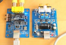
Here are two, the X-DA3 and L1387.
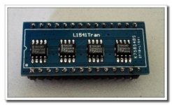
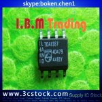
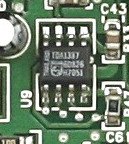
First it’s worth noting that finding genuine TDA1387 chips is a nightmare. If they say “Thailand” in bright white text they are fake. The ones I have look real but I'm suspicious because TDA1387 requires a current/voltage converter at the output. This can be accomplished without an op-amp using a small resistor network but results in a much lower output level, hence stacking the chips becomes necessary, however, in my case one chip per channel gives at least the same level output as the TDA5102A! Two TDA1387 chips on this board was way too loud for line-level so I suspect even these are fake.
X-DA3 - TDA5102A / SA9227
I removed the pointless output capacitors and 10K resistors to match the manufacturers recommended design. I added capacitance on the Vin side and two switches to play with the filter and pin 10 setting.
The SA9227 supports resolutions up to 32bit/384KHz. Completely pointless but oh so modern. More interesting the TDA5102A has two filters which can be switched. In my testing I could hear no difference. However the setting on pin 10 makes a significant difference to mid/top end, at least in 44100 and 48000Hz mode. I’m not sold on it, it sounds like an anti-aliasing filter is switched out and is perhaps tiresome with some music.
The TDA5102A trounces on the TDA1387 for dynamics and sound-stage. It's almost like there's a stereo separation enhancement at work. This is the noticeable benefit.
L1387 - TDA1387
Assuming the chips are genuine I can speak for the sound, which is warm with quite a mellow top-end. I feel it has a more taught and accurate bass response, which apparently is a characteristic of a NOS dac. For me it isn’t quite lively enough with a lack of energy. This would suit some music fine.
Overall
Both boards have as good as zero noise and if I’m honest the extra capacitors made no difference.
I’m not satisfied with either. I have a replacement SA9023 coming and from what I recall it beats both these DAC’s. I’ll report back!
Hi,
There are many USB dacs available on Aliexpress. The SA9023 isn't covered here but shall be added soon.
Here are two, the X-DA3 and L1387.
First it’s worth noting that finding genuine TDA1387 chips is a nightmare. If they say “Thailand” in bright white text they are fake. The ones I have look real but I'm suspicious because TDA1387 requires a current/voltage converter at the output. This can be accomplished without an op-amp using a small resistor network but results in a much lower output level, hence stacking the chips becomes necessary, however, in my case one chip per channel gives at least the same level output as the TDA5102A! Two TDA1387 chips on this board was way too loud for line-level so I suspect even these are fake.
X-DA3 - TDA5102A / SA9227
I removed the pointless output capacitors and 10K resistors to match the manufacturers recommended design. I added capacitance on the Vin side and two switches to play with the filter and pin 10 setting.
The SA9227 supports resolutions up to 32bit/384KHz. Completely pointless but oh so modern. More interesting the TDA5102A has two filters which can be switched. In my testing I could hear no difference. However the setting on pin 10 makes a significant difference to mid/top end, at least in 44100 and 48000Hz mode. I’m not sold on it, it sounds like an anti-aliasing filter is switched out and is perhaps tiresome with some music.
The TDA5102A trounces on the TDA1387 for dynamics and sound-stage. It's almost like there's a stereo separation enhancement at work. This is the noticeable benefit.
L1387 - TDA1387
Assuming the chips are genuine I can speak for the sound, which is warm with quite a mellow top-end. I feel it has a more taught and accurate bass response, which apparently is a characteristic of a NOS dac. For me it isn’t quite lively enough with a lack of energy. This would suit some music fine.
Overall
Both boards have as good as zero noise and if I’m honest the extra capacitors made no difference.
I’m not satisfied with either. I have a replacement SA9023 coming and from what I recall it beats both these DAC’s. I’ll report back!
Attachments
Last edited:
Where did you pick up the story that TDA1387s with 'Thailand' written on them are fakes? Most of mine have this marking and they so far have performed very well (subjectively) and there's been no noticeable deviation in how they behaved compared to the datasheet.
The L1387 DAC is amenable to many mods - active I/V and filtering are the ones I've explored, which fix the 'lack of energy' you noticed with the stock version. Even without active I/V you can improve on the bass by fitting a 470uF cap to each pin7 in parallel with the ceramic already on the PCB.
The L1387 DAC is amenable to many mods - active I/V and filtering are the ones I've explored, which fix the 'lack of energy' you noticed with the stock version. Even without active I/V you can improve on the bass by fitting a 470uF cap to each pin7 in parallel with the ceramic already on the PCB.
Hi,
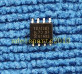
There are two fake "versions" from Thailand, some have the writing broken up around the philips logo (blatant fake). There is a post on the web somewhere describing the difference which is easily identifiable because the I/V resistor converter significantly limits output and the original chip can't output enough current with one chip. This is why 2-4 are required to get line-level. It is why I believe my NXP ones are also fake. I originally had two of these NXP chips per channel and is was massively over-powered for line-level.
TDA1387 have been out of production for a long time now, the writing will have decayed while the new ones is bright white from recent lasering. The fakes will work as a basic resistor ladder DAC but I doubt they have the auto-calibration stuff.
Bass is solid on the L1387, better than the TDA5102A - perhaps the 470uF cap is colouring the signal which works better for your amp/speakers. For me the let down is mid and upper range. Of course I have to consider if my chips are fake then there's no point comparing.
Last edited:
")
Mine look like the 'fake' ones you've shown, however they perform according to the DS in terms of output current. I have no idea why you think the original chip by itself can't output enough current.
The upper mid and HF is improved considerably by LC filtering, preferably at least 3rd order (CLC).
The upper mid and HF is improved considerably by LC filtering, preferably at least 3rd order (CLC).
Re: 470uF.
The datasheet states 1uF and this is what the board is using. If it made a difference to you it's probably because they aren't charging fast enough due to power side capacitance being too low. I stuck a 4700uF capacitor on the spare G & V+ pins. It made no difference (to my ears) however my 5V supply is already solid.
The datasheet states 1uF and this is what the board is using. If it made a difference to you it's probably because they aren't charging fast enough due to power side capacitance being too low. I stuck a 4700uF capacitor on the spare G & V+ pins. It made no difference (to my ears) however my 5V supply is already solid.
Mine look like the 'fake' ones you've shown, however they perform according to the DS in terms of output current. I have no idea why you think the original chip by itself can't output enough current.
The upper mid and HF is improved considerably by LC filtering, preferably at least 3rd order (CLC).
There's a very nice post on the web somewhere explaining it, using the original data-sheet. It's why the board takes 4 chips. I run 2 chips and it's louder than the TDA5102A (when it should be half the volume). 4 chips made the volume uncontrollable.
I'd rather not stick a filter on the output, might as well use delta-sigma in that case. It's probably the simple I/V converter killing the mid/treble.
Last edited:
...
Assuming the chips are genuine I can speak for the sound, which is warm with quite a mellow top-end. I feel it has a more taught and accurate bass response, which apparently is a characteristic of a NOS dac. For me it isn’t quite lively enough with a lack of energy. This would suit some music fine.
...
If the DAC is running NOS then you need a boost (~3dB I recall) at 20kHz to compensate for the sin c high freq rolloff of NOS DACs.
Cheers,
Jeff
I'd rather not stick a filter on the output, might as well use delta-sigma in that case.
Going to delta-sigma would lose you the excellent instrumental timbre this chip delivers, based on my own experience with various D-S chips.
It's probably the simple I/V converter killing the mid/treble.
The passive I/V isn't degrading the mid/HF in particular, rather it degrades the bass and the overall dynamics.
If the DAC is running NOS then you need a boost (~3dB I recall) at 20kHz to compensate for the sin c high freq rolloff of NOS DACs.
Yes, this boost is something that can be built into a following LC filter. I've found I can't duplicate the exact shape of the roll-off but I've gotten close enough.
Hi Paul, Can you explain what this feature is? It makes a big difference to mid/treble. The digital filter select has no noticeable impact.
Edit: ok, I understand now.
Abraxalito if you have those LC values to hand I'd be happy to try them, the board is otherwise being retired.
Edit: ok, I understand now.
Abraxalito if you have those LC values to hand I'd be happy to try them, the board is otherwise being retired.
Last edited:
If you go over to my Hackaday project there's the schematic for the filter and I/V stage : Audiophile-sounding DAC for almost no money | Hackaday.io
Emphasis is concept used when recording on to certain mediums to improve SNR/ range of the medium (not the original audio) where higher bands are gained and lower bands are attenuated. The best example of this is the RIAA filter used on vinyl records. The inverse of the fitler is implemented on the turn table to normalize the Audio so the response is flat again. Some CDs implement emphasis, so a lot of DACs can digitally 'demphasize' the data when the input is at CD sample rates (44.1 for instance).
If you go over to my Hackaday project there's the schematic for the filter and I/V stage : Audiophile-sounding DAC for almost no money | Hackaday.io
Hi @abraxalito, I have saved the schematic from that blog but it seems incomplete, there are 3 transistors used in the component list and in the schematic I can see only one; I would like to try the Anti-imaging and NOS droop filter, could you tell me what value is R44 and R45, is it in kohm or in ohm? also, what are I20 and I21 representing on the right side?
I imagine these values are for 4 paralelled TDA1387s, do I have to change some value in case of using 8 paralelled TDA's? I was thinking that R46 needs to be changed in this case
An externally hosted image should be here but it was not working when we last tested it.
you have also posted another NOS drop filter in another thread, this one was together with some low frequency compensation, which one do you thing is more accurate or appropiate for the real NOS drop? thanks
An externally hosted image should be here but it was not working when we last tested it.
Last edited:
I plan to update that schematic - its a simulation schematic from LTSpice with I20 and I21 as current sources and V17 as voltage source rather than explicitly shown (2 transistors per CCS, LED for voltage source). I'll work on a nice KiCad schematic over the next day or so and post it both here and on Hackaday.
R44 and R45 values are shown in ohms. Yes you're correct, R46 would be approximately halved for running with 8X TDA1387, though best wait for the updated schematic as I am currently using 600ohm for R46.
As regards the two schematics, the second one is load impedance dependent to some degree so the first one has a better chance of being the more accurate one - the anti-imaging filter is one and the same as the NOS droop correction there.
Here's the updated schematic with all component values filled in and strange value caps expanded into parallel combinations. Whilst so far I've used X7R 1206 caps in the filter I plan to try a build using 0805s.
To run this circuit with 8*TDA1387 will need a slight tweak to the lower current source to compensate for the excess (offset) current from 4 additional DAC chips. Its critical to keep the DC bias level at the output around 2.5V, much drift either side risks clipping on peaks or dips.
To run this circuit with 8*TDA1387 will need a slight tweak to the lower current source to compensate for the excess (offset) current from 4 additional DAC chips. Its critical to keep the DC bias level at the output around 2.5V, much drift either side risks clipping on peaks or dips.
Attachments
- Status
- This old topic is closed. If you want to reopen this topic, contact a moderator using the "Report Post" button.
- Home
- Source & Line
- Digital Line Level
- Impressions: USB DAC: TDA1387 NOS vs PCM5102A Delta-Sigma