I couldn't even buy the parts in the uk, never mind wages. However I have noticed parts are easier to buy at high volume prices even in lower volumes in the Chinese markets.
If you are really interested I could do a rough costing to see what it's likely to come out at buying parts from Uk low volume distribution.
Andy
Hi,
I think you don't need to go to that trouble as most people can source parts themselves, and may even prefer to build it themselves.
For me, I'm really looking a for a good PCB with good i2s routing, grounding etc and a buffered output too.
Are you interested in doing a PCB only ? If so, I'm definitely interested.
That would be my preference, I will need to build at least one up to test it so I need to look at the cost to me. Also I am not a programmer so if the modes you want need software config it might be a problem.
I will have a quick look and see what would be possible.
Incidentally crystal quality is mostly determined by the quality of the quartz and the cut. HC49 crystals can work very well with a High quality quartz and a colipits the cct driven at the correct level and with a LC resonator to optimise the Q of the circuit.
The low profile and SMT packages can make the cut more complex and hence more expensive. I recommend choosing the part via it's specification rather than package type.
Regards,
Andy
Hi,
It seems it will need software control. I wouldn't want a 12Mhz clock because it seems the best clock is either 24Mhz or 27Mhz. Still interested ?")
I didn't know you could get different crystal cuts in HC49 - anyone sell SC cut ? No chance I guess... I wrongly assumed they were all rubbish.
I use Euroquartz XO91 a lot - inexpensive and low jitter - so I'll try that first. The datasheet says less than 1ps rms but they don't say over what freq so I guess 10hz. Interestingly, Guido Tent claims the same for his xo module and they sound superb but I don't have a 12Mhz one of those. I have a Valab 12Mhz one to try too.
It seems it will need software control. I wouldn't want a 12Mhz clock because it seems the best clock is either 24Mhz or 27Mhz. Still interested ?
I didn't know you could get different crystal cuts in HC49 - anyone sell SC cut ? No chance I guess... I wrongly assumed they were all rubbish.
I use Euroquartz XO91 a lot - inexpensive and low jitter - so I'll try that first. The datasheet says less than 1ps rms but they don't say over what freq so I guess 10hz. Interestingly, Guido Tent claims the same for his xo module and they sound superb but I don't have a 12Mhz one of those. I have a Valab 12Mhz one to try too.
I am happy to wire it to a micro connector and put jumpers on to configure it, if you can find someone to program the micro. (I could make it compatible with an Arduno board or something like that. Arduino - Hardware)
Euroquartz do seem to be offering good value at the moment. I have been working with them on a set of high tolerance crystals in 500 Hz steps around 100MHz for a environmental dielectric sensor. They were much cheaper than the nearest competitor and were happy to supply custom parts in 500 off. This was in a low profile ceramic package as the part needs to go in a small enclosure and hostile environmental conditions.
However I don't imagine we will get 500 people together for a custom 24MHz or 12MHz part so I guess it will have to be something off the shelf. Still I know some tricks for optimising the performance of clock oscillators.
Regards,
Andy
Euroquartz do seem to be offering good value at the moment. I have been working with them on a set of high tolerance crystals in 500 Hz steps around 100MHz for a environmental dielectric sensor. They were much cheaper than the nearest competitor and were happy to supply custom parts in 500 off. This was in a low profile ceramic package as the part needs to go in a small enclosure and hostile environmental conditions.
However I don't imagine we will get 500 people together for a custom 24MHz or 12MHz part so I guess it will have to be something off the shelf
. Still I know some tricks for optimising the performance of clock oscillators.Regards,
Andy
As an initial discussion document I have thrown a circuit together. This has not been checked so probably contains lots of errors but at least it provides a concept.
It includes screw terminals for all the I/O signals. Twisted pairs are probably the best way to bring signals in and out. A coax may be needed for the clock input if you use an external clock PCB.
I have put a standard clock OSC on the PCB but can upgrade this if a on board high quality clock option is preferable.
I have put on phono type connectors and optical connectors as I had PCB patterns for them however a BNC is possible but I will have to make the pattern which takes a long time. So I will do this if there is interest.
The board is configured to expect software control. If we want to use all the input then this is required. If a hardware option is wanted I will have to add lots of jumpers to configure it.
I have buffered the inputs and outputs, the inputs may need termination resistors depending on the speed at which the signal is being driven. However depending on the source impedance this could cause the logic level to be too low so they may need to be removed.
As I said this is just a first draft and in no way intended to be considered complete or checked.
Comments welcome.
Regards,
Andy
Attachments
Fast !
The datasheet says the clock must be between 12 and 24, or 27Mhz but you have noted 11.2896 ?
No pulse transformers on the inputs ?
It might be on this thread, or elsewhere, but it seems the higher clock freq is better.
On the thread here,
http://www.diyaudio.com/forums/digital-line-level/180336-wolfson-wm8805-i2s-tda1541a-nos.html
it was noted that performance improved considerably with an xo, and this is very credible of course, so perhaps you should design it around smd ( like XO91 ) or Tent labs dip, plus any clock circuit improvement possible.
Finally, all the decent regs these days are tsot, like the adp151, so you should design for this I think.
Other than that, hopefully others more knowledgeable than me will comment...
Thanks !
BTW I didn't check the pin connections but I assume you did ;-)
Last edited:
Hi,
Crystal came from an old design and I forgot to update the freq. I'm not sure I have a XO91 PCB footprint but I can make one if that is the preferable part. Also if you intend to use the on board oscillator I will design a discrete osc circuit to run it rather than use the CMOS one inside the WM8805. I imagined from your description that you would use an off board osc so didn't bother putting any effort into the on-boad osc.
PSU was also one I had available but I can easily change it to a ADP151.
I have used these parts before so unless the pins have moved they should be OK.
Driver software is the biggest problem and how to debug the board.
Regards,
Andrew
My experience of pulse transformers has been mixed. They don't always seem to improve the situation but I guess they do provide isolation to DC and L.F noise such as ground loops.
Do you have a part in mind as I haven't used any recently so don't know what's good. I think it was a Schott 22133 I used last time but I don't know where I could buy them in low volumes.
Regards,
Andrew
Do you have a part in mind as I haven't used any recently so don't know what's good. I think it was a Schott 22133 I used last time but I don't know where I could buy them in low volumes.
Regards,
Andrew
Hi,
I'd definitely want the option of onboard xo, and ideally it should have smd pads for 5x7 xo (and smaller- there are some tiny ones available in japan with ultra low jitter) and also holes for a square dip package like Tent labs/feeding in an external clock.
The clock should get its own reg and again that would be tsot for adp150 or tps79333dbvr or similar. I don't know if/how a clock output can be improved but if you know a tried and tested way then that would be awesome. Of course, low jitter is the main goal.
An alternative to the reg is to use a potential divider (say 5.1K and 22K) to drop 5v to 4V and feed that into the base of a bc550 with a 100uF cap from the base to ground. This gives 3.3V output and it's a a very effective noise killer.
Pulse transformers - off the top of my head so maybe my part nos might be wrong - the Newava s2283 is great and the Murata DA101C is also very good.
I forgot to say, for input, I think some people might be okay with RCA but I'm not. So, let's say one optical toslink for PC, two bnc for cd and digital player, and one rca for the couldn't-care-less-must-be-convenient people ? Perhaps an XLR is going to be necessary too if this board is going to become popular. Sorry if this is more work but it's really a must.
Thanks !
Hi,
Well, software is going to be a headache it seems. There's no available code for LCDuino. Linux Works says it is hard to program, so it must be extremely hard to program ! He says he hasn't given up... but that sounds like he wants to !
There might be code for programming through Linux on the Wolfson site. I'm not exactly new to Linux but I'm far from feeling comfortable with it and rolled back to Windows after a few months with it.
So, what to do... well, I'll check out the Wolfson site when I have a bit of time tonight, but it does seem Wolfson have made the WM8805 a tough nut for DIYers to crack.
Cheers,
Tom
Linux isn't really a good way to control hardware. You have to create complex drivers that work though the scheduling of a multitasking operating system. I am fairly sure there is no code on the Wolfson site.
I had a look at the dev board to see if I could make it compatible with Wolfsons support software however they have put a micro co roller the board an the PC talks to that via USB. So that won't work.
It looks like we need to write the firmware from scratch, I can put a micro and even a display on if we can find some one to code it.
Andrew
Hmmm, would be cool to get someone jump in for the code.
Member glt H i F i D U I N O
or member linuxworks (i think he plans a multiple s/pdif in-out platform) might be approached....
Member glt H i F i D U I N O
or member linuxworks (i think he plans a multiple s/pdif in-out platform) might be approached....
It looks like we need to write the firmware from scratch, I can put a micro and even a display on if we can find some one to code it.
If you put a Cortex M0 on the board (say an LPC1113 just as example) then you can use the code I'm planning to write. I'm developing a DAC using an WM8805 and will get around to writing that code over the next couple of months. However the caveat is I'm not interested in sample rates up to 192k - so anyone wanting more than 96k will have to extend the code themselves. As far as I recall the WM8805 has to be gently coaxed into locking at the higher rates.
Hi,
96Khz is fine with me because I have no 192 sources. What about everyone else ?
.... and yeah, the datasheet seems to indicate that 192 can be a pita and 176.4 even more so (page 29).
I found Linux support for WM8804 but that is one in & out so no good for me, or, I'm sure, many others.
So, do we wait for our generous helper Abraxalito to do the code before moving ahead ? It would seem wise since the code is essential...
My Taobao board arrived so I quickly hooked it up and took some snaps. It is locked onto a 96/24 optical source. I won't get a chance to test it properly until the weekend.
The clock is 5V which I'm sure must be too high - surely this girl needs 3.3V ?
An externally hosted image should be here but it was not working when we last tested it.
An externally hosted image should be here but it was not working when we last tested it.
An externally hosted image should be here but it was not working when we last tested it.
An externally hosted image should be here but it was not working when we last tested it.
Last edited:
So, do we wait for our generous helper Abraxalito to do the code before moving ahead ? It would seem wise since the code is essential...
I suggest you go ahead and slap one of these CPUs down on the board. I'll want to use the I2C (2 wire protocol, Wolfson don't call it I2C coz they'd have to get a license I guess!) as that has hardware support on the LPC111X. If you don't much like the 48pin fine pitch package then NXP are working on some more DIY-friendly packages but I have no idea if they're available yet.
The relevant datasheet is here:
http://www.nxp.com/documents/data_sheet/LPC111X.pdf
<edit> Another alternative if you don't fancy putting the CPU on the board itself is to make your board like a shield (Arduino style) that piggy backs onto an already available Cortex dev board. If you prefer this route, I'll suggest such a board and give you pinouts etc. I'll be a cheap one (like under $10).
Last edited:
The NXP one looks good - SO20 is easy enough. It seems worth waiting for the most diy friendly one and it also means it'll probably stay in production for longer.
Personally I'm happy to have the cpu on the same board but I'd hope the design creates a separate ground plane for it, so the noise it produces doesn't contaminate the wm8805 ground. This would mean using jumpers across the two.
Something like AMB does with the volume control board :

However, a piggyback is also good. What other factors should help us choose ?
Personally I'm happy to have the cpu on the same board but I'd hope the design creates a separate ground plane for it, so the noise it produces doesn't contaminate the wm8805 ground. This would mean using jumpers across the two.
Something like AMB does with the volume control board :
However, a piggyback is also good. What other factors should help us choose ?
Last edited:
If you opt for the DIY friendly package then I have no idea when it will actually arrive from NXP. Looking at their website, it seems the TSSOP20 is nearer to production than the SO20. SO20 is still at 'development' status whereas TSSOP20 is at 'qualification' (which means they're currently sampling).
Hi,
Well, I'm keen to keep this as a PCB project rather than a completed board, so that means diy friendly. I can do little tsot but a 48 pin is too much, so maybe a completed piggyback is the best option ?
If people want a fully completed board they can get the Ebay one or go for IanCanada's completed fifo Ti DIX spdif board (US$90).
I'd be very interested to know if the WM8805 is likely to be better or worse than Iancanada's project.
http://www.diyaudio.com/forums/digi...ifo-project-ultimate-weapon-fight-jitter.html
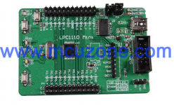
Here's a shot of a relatively cheap CPU board - the advantage of going for this one is it has on-board USB interface which allows programming via FlashMagic without needing any kind of external adaptor. Its slightly smaller than a credit card. If you'd like to go with this then the top board would need two 24pin dual row headers on it, one top and one bottom.
IanCanada's project is a little more ambitious in that he's implemented a FIFO to control jitter.
IanCanada's project is a little more ambitious in that he's implemented a FIFO to control jitter.
Attachments
- Status
- This old topic is closed. If you want to reopen this topic, contact a moderator using the "Report Post" button.
- Home
- Source & Line
- Digital Line Level
- WM8805 upgrade board (cs8414 pins) - dissapointed