It's a definite candidate ! is this your preferred choice ?
I'm not the only one interested in this pcb so I don't want to dictate how it turns out.
So I'd like to hear from anyone else following this thread about what they'd prefer. Please add your comments if you have a preference or whatever.
In the meantime, NXP have a HK office, so I'll contact them and ask them to find out when/if the so20 might be available.
NXP Semiconductors Hong Kong Ltd.
8/Floor, General Garment, Building, 100-110, Kwai Cheong Road, Kwai Chung, N.T.Hong Kong
Tel:+852 2319 7888
Fax:+852 2319 7700
Well as I mentioned earlier, I'm developing a DAC design. It will also use a CPU and be piggy-backed and I'm going to go with that board for reasons of cheapness (its about $8) and ease of availability (the manufacturer is a 15min cycle ride from my home and speaks good English). So that would mean maximum commonality between the two projects which bodes well for how little extra time I'd need to spend supporting this one ")
But sure, other suggestions welcomed - if anyone finds a better one then I might jump ship myself...
But sure, other suggestions welcomed - if anyone finds a better one then I might jump ship myself...
Hi,
The 48 pin quad flat pack is listed on NXP web site as being in production (don't know if this is true). Would this be OK for DIY.
LPC1113FBD48 :: NXP Semiconductors
abraxalito are you able to see if its available from you local company?
Would this be a suitable alternative to the piggy back?
I am happy include the piggy back if that works out as the best solution, just looking at other options.
Was there a particular reason you chose this platform abraxalito. It looks like allot of processing power to configure a DAC and DIR do you have a complex display to support as well.
Looks like you need the LXexpresso dev kit to work with this part and I couldn't find a price. Do you have a development environment that will work?
Thanks for offering to let us piggy back on your development work.
Regards,
Andrew
The 48 pin quad flat pack is listed on NXP web site as being in production (don't know if this is true).
Yes, its true, its been available for over a year. I have several on boards and a tray full for when I eventually get around to building my own PCBs.
Would this be OK for DIY.
The pitch is very fine (0.5mm) - I haven't attempted to solder one myself. I think many DIYers would shy away from this. TSSOP is a little daunting but do-able, that's 0.65mm.
Was there a particular reason you chose this platform abraxalito. It looks like allot of processing power to configure a DAC and DIR do you have a complex display to support as well.
I chose the platform because I'm already familiar with it with my own projects. Its a lot of processing power but that's cheap these days - the device itself costs under $2 and if you don't want all that horsepower it can be run at much slower clock speeds than its rating (50MHz) which saves power and reduces noise. Another reason I like it is the datasheet is one of the few that gives reassurance about its EMC signature. Its also able to run some fairly simple DSP tasks if desired - like an OS filter. There's a lot of flexibility there for the budding DIYer without breaking the bank - the cost is the same here as that of the WM8805.
No, I'm not going to use it to drive a display. I plan to use its DSP capabilities to experiment with custom digital filters and DAC linearization tricks.
Looks like you need the LXexpresso dev kit to work with this part and I couldn't find a price. Do you have a development environment that will work?
I'm currently using a dev environment which was provided to me when I bought another dev board (Keil) - but that's fairly expensive. You could use LPCexpresso (I think the board is around $30?) or you could download the free tools from CooCox -
Free and open ARM Cortex M3 and Cortex M0 embedded development tools
Hi
I have progressed a bit on the Schematic.
Changes:-
The Inputs are now
One Phono SPDIF no pulse transformer
One BNC with pulse transformer
One Optical
I have spaced these on the input multiplexer as inputs 2,4,6 with all the other inputs grounded. However as crosstalk is still likely to induce extra jitter if you plan to attach more than one input at a time, I should probably think of some better way of isolating the unused inputs. (Is this a requirement?)
I have updated the XTAL freq.
To Do:
New PSU reg
Crystal oscillator module option.
(I can't improve these, I was thinking of a discrete oscillator but actually a discrete oscillator will require loads of parts and is probably not ideal for DIY)
CPU
It looks like the piggy back NXP is the way to go then. Do you have a pin out and PCB layout drawing for it?
Other options we may need:-
Buttons to select input?
buttons to select sample rate?
LEDs to indicate status:-
Board options:-
2 layer it could easily be tracked on 2 layers but its not optimal for signal integrity.
4 layer - would provide better signal integrity very easy tracking but costs much more.
What is the preference?
Other options:-
Do we want a DAC?
Software
It has been 15 years since I did any programming in C and 20 years since I did any assembler (Z8) so I am not confident to even modify your code. I am assuming you will write in C, is this the case?
I'm not even confident I could set up the programming environment for firmware development as the last time I did this I blew the code into EPROMS.
I will give it a try if needs must but I can't be sure of success.
Regards,
Andrew
I have progressed a bit on the Schematic.
Changes:-
The Inputs are now
One Phono SPDIF no pulse transformer
One BNC with pulse transformer
One Optical
I have spaced these on the input multiplexer as inputs 2,4,6 with all the other inputs grounded. However as crosstalk is still likely to induce extra jitter if you plan to attach more than one input at a time, I should probably think of some better way of isolating the unused inputs. (Is this a requirement?)
I have updated the XTAL freq.
To Do:
New PSU reg
Crystal oscillator module option.
(I can't improve these, I was thinking of a discrete oscillator but actually a discrete oscillator will require loads of parts and is probably not ideal for DIY)
CPU
It looks like the piggy back NXP is the way to go then. Do you have a pin out and PCB layout drawing for it?
Other options we may need:-
Buttons to select input?
buttons to select sample rate?
LEDs to indicate status:-
- input
- sample rate
Board options:-
2 layer it could easily be tracked on 2 layers but its not optimal for signal integrity.
4 layer - would provide better signal integrity very easy tracking but costs much more.
What is the preference?
Other options:-
Do we want a DAC?
Software
It has been 15 years since I did any programming in C and 20 years since I did any assembler (Z8) so I am not confident to even modify your code. I am assuming you will write in C, is this the case?
I'm not even confident I could set up the programming environment for firmware development as the last time I did this I blew the code into EPROMS.
I will give it a try if needs must but I can't be sure of success.
Regards,
Andrew
The Inputs are now
One Phono SPDIF no pulse transformer
One BNC with pulse transformer
One Optical
It sounds with all these connectors on the board that the physical size won't be suitable as a piggy back. Do you have dimensions available yet? With such a (seemingly) large board it would make a lot more sense mechanically that the CPU was the daughter module, which would mean choosing a different CPU board.
Buttons to select input?
buttons to select sample rate?
Surely sample rate is indicated by the incoming SPDIF rate? I have no wish to spend time implementing switch debouncing so with multiple inputs, let's just have one button per input (rather than a single button which toggles through the inputs).
2 layer it could easily be tracked on 2 layers but its not optimal for signal integrity.
I'd recommend going for 2 layers.
Do we want a DAC?
Wow, spec creep
If you do I can advise.It has been 15 years since I did any programming in C and 20 years since I did any assembler (Z8) so I am not confident to even modify your code. I am assuming you will write in C, is this the case?
No, my C coding is incredibly rusty and I can't see the point for such low-level code. ARM assembler it most certainly is for me. I predict that's the future for hardware-related things - C code's biggest draw has been portability, as the future's very definitely ARM then assembler will be just as portable (maybe even more so) than C.
I had imagined a board with a separate are for the CPU to plug in. If the intention is for this to be a very high spec recover then we probably want the radiated noise from the CPU as far away as is practical.
Sorry wasn't thinking straight on the sample rate. Do we want LED indicators.
Single buttons seems like a good approach.
The reason I asked on the DAC is that if you are designing something as well we could combine them. Was it a WM8741 you were planning to use as I have used these before so have PCB parts and a layout available. Happy either way. I am doing this more to keep my hand in rather than any requirement for the actual completed project.
in term of footprint if we make it half eurocard size then it should be easy to find enclosure to fit. It depends a bit on the size of the piggy back CPU and how much overlap of the CPU and reciever we are happy with.
Regards,
Andy
Hi,
For me, no DAC, and 3 inputs is acceptable if it is with two isolated bnc and one optical. I guess you wanna use rx2 pin 27, rx4 pin 25, rx6 pin 23 ? Why not add the rca to rx1 pin 2 ?
The adp151 regs require smd 2uF x7r on input and output. Better (lower noise) to use Nichicon ple solid polymer cap bypassed with 0.1 uf x7r ?
The oscillator is extremely important. I hope the plan is to use a high frequency ( 24 Mhz or 27 Mhz ) if for no other reason than it gives greater choice and allows the lowest phase noise xo possible. Perhaps we should spec this exactly ? Anyone know a very low phase noise xo suited to this ? My pick would be Crystek cchd-957 but it's not available in the desired freq.
The oscillator should have its own adp150 (150mA) or adp151 (200mA), ferrite, etc with a 22r in the path to avoid bounce ?
BTW, I tested out the board I bought on Taobao this weekend. I'm using it to feed an AMB y2 dac with src4192 and Tent labs clock. This means I only need the bclk, lrclk and data connections because they share gnd from the Sigma11 psu and the src4192 doesn't want the mclk.
Anyway, it works and sounds good too. Quite surprised. I'm listening through HD650 so it's hard to judge space depth etc, but the detail is excellent, with perhaps just a fraction too much sibilance on the i2s 24 bit output. So I'm going to try changing some of the components on the board to see what, if any, difference it makes.
Cheers,
Tom
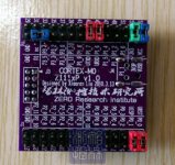
I had imagined a board with a separate are for the CPU to plug in.
That would be fine yes - did you look at the picture I shared? It has the connectors on the top side, so needs a board plugging in above it. Its natural to me that the upper board is the same or smaller in size so the whole arrangement's not top heavy.
If the intention is for this to be a very high spec recover then we probably want the radiated noise from the CPU as far away as is practical.
Radiated noise is less of an issue than conducted - the cpu itself is such a small area that it can't form an effective antenna without the use of connecting wires. The LPC111X datasheet is one of the few that has some radiated noise measurements.
Sorry wasn't thinking straight on the sample rate. Do we want LED indicators.
They'd be useful yeah.
The reason I asked on the DAC is that if you are designing something as well we could combine them. Was it a WM8741 you were planning to use as I have used these before so have PCB parts and a layout available. Happy either way. I am doing this more to keep my hand in rather than any requirement for the actual completed project.
As it happens the DAC design I've been working on for about a year now is based on TDA1545s, multiples in paralllel. I haven't actually heard the Wolfson parts but as they're S-D architecture I won't be holding my breath. If you're seriously interested in laying out my DAC design then I have no objection
It would be rather likely to slow down the development - does anyone mind about that?in term of footprint if we make it half eurocard size then it should be easy to find enclosure to fit. It depends a bit on the size of the piggy back CPU and how much overlap of the CPU and reciever we are happy with.
The piggy-back CPU I have in mind is this one:
Attachments
Hi,
Looking at the data sheet for the sample rate a switch is required to reconfigure the PLL for 192k input if this is required. I knew there was a reason this was in my mind - do we want this option?
No DAC then will make it much easier to fit on a euro card. I like the 8741 with the low roll off filters and its random output filter linearisation by using several switched cap stages, it was clearly a derivation of the dCS ring DAC which did sound better but was very complex to manufacture an hence expensive. I guess you want to develop you own filters on a non bit stream DAC.
I found this tcxo which is has the highest stability of the parts that I can find off the shelf at 0.5ppm, that also have a configuration listed in the data sheet. I tried Farnell RS and Rapid online. Digikey and Mouser tend to have high minimum order requirements. I am open to other options if anyone has any ideas.
http://www.farnell.com/datasheets/94400.pdf
There is also a 26Mhz part but that requires calculation of the PLL configuration registers and it seems like a bit of a risk since the data sheet is not very clear on the requirements for the PLL when used with the SPDIF input.
The 27MHz part is not nearly as stable presumably as it is designed for video where this level of stability would be massively over the top.
The 26Mhz part is worth considering if we think we could get the PLL configured what do you think?
Regards,
Andrew
Looking at the data sheet for the sample rate a switch is required to reconfigure the PLL for 192k input if this is required. I knew there was a reason this was in my mind
- do we want this option?No DAC then will make it much easier to fit on a euro card. I like the 8741 with the low roll off filters and its random output filter linearisation by using several switched cap stages, it was clearly a derivation of the dCS ring DAC which did sound better but was very complex to manufacture an hence expensive. I guess you want to develop you own filters on a non bit stream DAC.
I found this tcxo which is has the highest stability of the parts that I can find off the shelf at 0.5ppm, that also have a configuration listed in the data sheet. I tried Farnell RS and Rapid online. Digikey and Mouser tend to have high minimum order requirements. I am open to other options if anyone has any ideas.
http://www.farnell.com/datasheets/94400.pdf
There is also a 26Mhz part but that requires calculation of the PLL configuration registers and it seems like a bit of a risk since the data sheet is not very clear on the requirements for the PLL when used with the SPDIF input.
The 27MHz part is not nearly as stable presumably as it is designed for video where this level of stability would be massively over the top.
The 26Mhz part is worth considering if we think we could get the PLL configured what do you think?
Regards,
Andrew
Hi,
Unfortunately, low ppm doesn't always assure low ps and the datasheet doesn't spec phase jitter.
The lowest jitter xo I can find in a suitable frequency is Tent Labs' 27.000Mhz. That is also available in 12.000Mhz.
Cheaper options I know work are Euroquartz xo91, and RS lists that in 24.000Mhz and 12.000mhz.
Buy SMD Crystal Oscillator Oscillator, 4 pad, XO91, 24.000MHz Euroquartz XO91050UITA-24.000 online from RS for next day delivery.
Farnell also has that in 12Mhz and 24Mhz.
http://www.euroquartz.co.uk/Portals/0/xo91.pdf
So contrary to what I said before, perhaps 12Mhz might be the best choice after all, unless we can find a lower jitter xo ?
EDIT :
Here's a possible cheaper 27.000mhz substitute for Tent's. MEC VM53S3-27.000-2.5/-30+75 (but no 12.000Mhz that I can find)
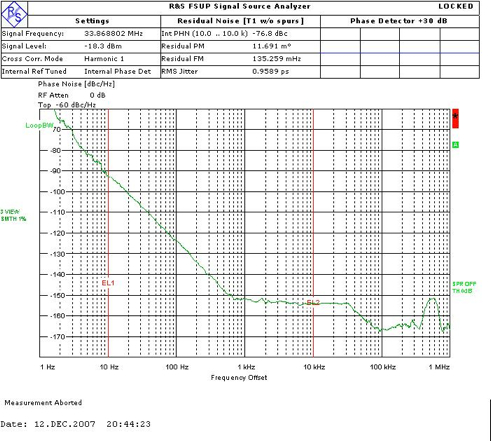
-80dB at 10Hz, -105dB at 100Hz, -125dB at 1khz, -140dB at 10Khz
http://docs-asia.electrocomponents.com/webdocs/0d5a/0900766b80d5a4cf.pdf
http://hongkong01.rs-online.com/web/p/controlled-oscillator/6720791/
I wonder if we contact Euroquartz, they might already make the xo91 in 27.000Mhz...?
Unfortunately, low ppm doesn't always assure low ps and the datasheet doesn't spec phase jitter.
The lowest jitter xo I can find in a suitable frequency is Tent Labs' 27.000Mhz. That is also available in 12.000Mhz.
Cheaper options I know work are Euroquartz xo91, and RS lists that in 24.000Mhz and 12.000mhz.
Buy SMD Crystal Oscillator Oscillator, 4 pad, XO91, 24.000MHz Euroquartz XO91050UITA-24.000 online from RS for next day delivery.
Farnell also has that in 12Mhz and 24Mhz.
http://www.euroquartz.co.uk/Portals/0/xo91.pdf
So contrary to what I said before, perhaps 12Mhz might be the best choice after all, unless we can find a lower jitter xo ?
EDIT :
Here's a possible cheaper 27.000mhz substitute for Tent's. MEC VM53S3-27.000-2.5/-30+75 (but no 12.000Mhz that I can find)
-80dB at 10Hz, -105dB at 100Hz, -125dB at 1khz, -140dB at 10Khz
http://docs-asia.electrocomponents.com/webdocs/0d5a/0900766b80d5a4cf.pdf
http://hongkong01.rs-online.com/web/p/controlled-oscillator/6720791/
I wonder if we contact Euroquartz, they might already make the xo91 in 27.000Mhz...?
Last edited:
Thanks for the ocs module info. I haven't used them before and the phase jitter perfirmance wasn't listed so I went with fequency stability as the next best indicator.
Unfortunately I no longer have acess to anything I could measure the phase noise on so can't test to see if the temp controlled devices are better or not.
I know you asked for the output to be buffered however the measurements I did on logic gates some time ago indicated the introduce between 40 to 100 ps of phase noise per gate. If this really is the most critical requirement we probably need a much lower noise buffer than a standard gate.
However I doubt the internal electronics of the WM8805 is this quite.
Regards,
Andrew
Hi,I know you asked for the output to be buffered however the measurements I did on logic gates some time ago indicated the introduce between 40 to 100 ps of phase noise per gate. If this really is the most critical requirement we probably need a much lower noise buffer than a standard gate.
However I doubt the internal electronics of the WM8805 is this quite.
Regards,
Andrew
Interesting test ! Do you remember what logic gates you tested ? I've been using 74VHC04.... maybe I can find better...
Well, the buffer was intended to allow longer i2s lines to connect into a DAC ... but if it is going to add substantial amounts of noise then maybe we'll have to let any end user add a buffer themselves and not design one in ?
So maybe no output buffer after all ?
Here's the datasheet for Nichicon LE ultra-low esr caps.
http://www.farnell.com/datasheets/51380.pdf
The 820uF 6.3V might seem like overkill but I've used them and they sound very good.
The datasheet says the case diameter is 8mm, the height is 12mm and the lead spacing is 5mm and lead diameter is 0.6mm. So it'd be great if you had a space for one of these either side of each reg and another on the power input. 5 in total. of course, the builder can choose a cheaper cap if they want.
Seems possible ?
Last edited:
One last thing - for the output, I think we should have the option of ordinary pin out holes and also use u.fl receptacles so coax cable can be used.
Like this :
Buy Connector RF Connector,RF/coaxial,hirose,U.FL,receptable,smt,10pack Hirose U.FL-R-SMT-1(10) online from RS for next day delivery.
Cheers,
Tom
Like this :
Buy Connector RF Connector,RF/coaxial,hirose,U.FL,receptable,smt,10pack Hirose U.FL-R-SMT-1(10) online from RS for next day delivery.
Cheers,
Tom
Hi,
Manflu eh ? It's a killer .. ;-) No worries - take it easy - there's no hurry. Haste often leads to errors.
I contacted Euroquartz - I got a reply from MERCURY ELECTRONIC IND. CO., LTD in Taiwan, who say they are Euroquartz's business partner.
I gave them the info they asked for but so far I have had no reply, so I think we can scratch Euroquartz from the list and go for the 27Mhz MCE / Tent Labs xo's.
Cheers,
Tom
[...]go for the 27Mhz MCE / Tent Labs xo's.
I somehow when studiyng the datasheet got the impression that using a frequency synchronous with the output MCLK and the input CLK (or a integer value of it) performance will be better.
Of course this applies only to one family of fs, either 44.1-88.2-176.4 or 48-96-192 kHz.
PLL_K value in any case would be an integer value. Eg 8 if f2 is 90.316MHz and Clock is 22.5792MHz (512xfs at 44.1)
Hi,
Can you say where on the datasheet you got this from ? I didn't see that anywhere but I probably missed quite a lot and need to re-read it.
I'd love to use a 24.576 (huge choice) but it says 12 to 24 and 27 so I assume it means not 24.576. If it'll work with 22.5792 that's great, except the choice of xo's in this frequency at Farnell and RS is zero. Yep, none, not one. It does mean we can use the CCHD-957 though so that'd be excellent.
BTW I've emailed suppliers and Euroquartz etc but got nowhere with the 22.5792. The unloved freq.
So what to do.
- Status
- This old topic is closed. If you want to reopen this topic, contact a moderator using the "Report Post" button.
- Home
- Source & Line
- Digital Line Level
- WM8805 upgrade board (cs8414 pins) - dissapointed