Yea, casing this beast can be quite a challenge. After building/running the 'Beast' (the huge machined aluminum case I built a few pages back) which relied on a 16"x10" 3/8" plate with sinks on the end for cooling, it's the only way to go. As Qusp noted downstream of my photo, the end caps aren't even really needed. I've ordered similar plates for my other cases which are stock shells.
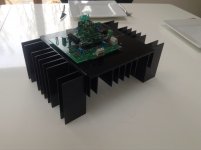
Ok got new heatsinks and now the temperature is reduced significantly - after more than an hour I can keep my hands on the sink near the mosfets without pain.
Misterrogers, I saw your comments earlier in this thread on enclosure - but did not manage to find any picture of your finished enclosure - perhaps i didn't search right") . When you say, end caps are not really needed, do you mean the output capacitors - are you running without them? I remember OPC and Qusb talk about it earlier in the thread - but didn't dare to try it.
. When you say, end caps are not really needed, do you mean the output capacitors - are you running without them? I remember OPC and Qusb talk about it earlier in the thread - but didn't dare to try it.
Misterrogers, I saw your comments earlier in this thread on enclosure - but did not manage to find any picture of your finished enclosure - perhaps i didn't search right
. When you say, end caps are not really needed, do you mean the output capacitors - are you running without them? I remember OPC and Qusb talk about it earlier in the thread - but didn't dare to try it.Attachments
Haven't posted finished pics yet because it's still running open I hope to close it up soon, but I've been diving deep into the USB receiver, clocks, Isolator, battery power vs. PS side of things. That side of the build has literally changed or been tweaked every week. There's hope though - I can see light at the end of the tunnel.
My comment on the end caps not being needed was related to the end cap heatsinks on my custom case. The thick base plate has enough mass/dissipation to handle the mosfet/resistor dissipation requirements.
I like your heatsink - looks aggressive!
I hope to close it up soon, but I've been diving deep into the USB receiver, clocks, Isolator, battery power vs. PS side of things. That side of the build has literally changed or been tweaked every week. There's hope though - I can see light at the end of the tunnel.My comment on the end caps not being needed was related to the end cap heatsinks on my custom case. The thick base plate has enough mass/dissipation to handle the mosfet/resistor dissipation requirements.
I like your heatsink - looks aggressive!
Until I find a more permanent solution for enclosure I was thinking of mounting transformers and power supply like below. I am in doubt if it is ok to mount the two 40v transformers on top of each other - am I ok here or do I need to consider a min. distance between them?
Wife is working late today - so hoping I can get this beast up and running tonight
Wife is working late today - so hoping I can get this beast up and running tonight
Attachments
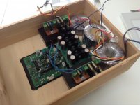
Qusb, Thanks for your comments. Yes you are right the PH regs where getting too warm mounted that way - i have now placed them in upright position.
Reg transformer, I saw OPC suggested Antek AN-0540 which has 40v sec.
I got all hooked up yesterday and are now playing music I can't believe I got all those tiny resisters and caps soldered correctly in first go - I could not have done it without all the guidance and good advice in this thread - thanks a lot
Reg transformer, I saw OPC suggested Antek AN-0540 which has 40v sec.
I got all hooked up yesterday and are now playing music
I can't believe I got all those tiny resisters and caps soldered correctly in first go - I could not have done it without all the guidance and good advice in this thread - thanks a lotahh OK that makes sense, the Antek are rated in a bit of an odd way, so generally sag some under full load, so they should be fine. the NTD1 sucks more power and thus creates more drop than one might expect of an IV stage anyway, but I dont know how comfy i'd be with something like a 40v plitron or sumR. either way you could increase Vout to 46-47vdc ius need be and be fine.
good job, glad you are up and running!
btw its qusp with a p, no B also no capitalization, but thats just nitpicking
good job, glad you are up and running!
btw its qusp with a p, no B also no capitalization, but thats just nitpicking
if they arent too hot now dont worry about it, it will depend on your mains and the particular transformer. the antek will probably be fine, but some tx will be rated (correctly) at full load and so may rise somewhat with a slightly lower load.
STFU putrified soybean product man
STFU putrified soybean product man
Qusb, Thanks for your comments. Yes you are right the PH regs where getting too warm mounted that way - i have now placed them in upright position.
Reg transformer, I saw OPC suggested Antek AN-0540 which has 40v sec.
I got all hooked up yesterday and are now playing music
Glad to hear you're up and running!
As qusp mentioned, the Antek transformers tend to sag a little more than others, so you should be fine there. I'm using the same parts and they've been great for the past few years.
It would be worth checking your various rail voltages with a DMM though just to be sure.
Measure the unregulated voltage on the first filter cap and note it down. If it's more than 10V drop across the regs (the difference between your unregulated and regulated rails) you should probably shift some of that dissipation off onto the I/V itself assuming you have capacity in your I/V heatsink.
The sweet spot for this circuit is between 44V and 48V, so try and stay in that range.
The current through each reg is roughly 230mA, so as long as you keep the voltage drop to under 10V you'll be dissipating less than 2.5 watts on those little regulator heatsinks which should be fine.
Enjoy the new I/V, and please do report back when you've done some good listening!
Cheers,
Owen
balance to SE conversion for the NTD1
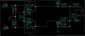
I am thinking of building a balance to SE converter for my ntd1, with LME49990s since I have some lying around. At some point I remembered than opc's lpuhp utilizes that.
So is the below schematic (part of opc's lpuhp) correct to be used for this purpose?
I'm thinking of supplying it with 18V "stolen" from the ntd1.
What do you think?
Attachments
depends on your caps, the LPUHP in balanced input format has pretty low (lowish) input impedance, so you need reasonable sized caps on the NTD1. myself i'd be building a balanced amp before adding a BAL-SE to the NTD1, but thats just me. seems a waste, may as well have just used the lme49990 as your IV... my prejudice on this matter are fairly well known
Last edited:
I hear you, but I already have three amps, all SE input and I wouldn't want to build another one at least for now. I prefer to first build me a dac/iv/buffer.
The goal is to have after the ntd1 a switch which will send the signal to the converter or directly out to xlr connector. This way I will have the option to use any balanced or unbalanced amp.
Could you elaborate about the caps?
The goal is to have after the ntd1 a switch which will send the signal to the converter or directly out to xlr connector. This way I will have the option to use any balanced or unbalanced amp.
Could you elaborate about the caps?
you need to size your output caps and the resulting 3dB point, keeping in mind the input impedance of the LPUHP.
Owen, seems this question comes up quite a bit, I wonder if a suitable discrete BAL-SE stage in keeping with the style of the NTD1 (ie massive overkill) could be devised.
Owen, seems this question comes up quite a bit, I wonder if a suitable discrete BAL-SE stage in keeping with the style of the NTD1 (ie massive overkill) could be devised.
you need to size your output caps and the resulting 3dB point, keeping in mind the input impedance of the LPUHP.
The reason is I want to avoid the above part..
Glad to hear you're up and running!
....
Enjoy the new I/V, and please do report back when you've done some good listening!
Cheers,
Owen
Sure will report back after I have listened further. Currently i only have a single ended amp and are tapping signal from 1 phase of the I/V - well aware off the limitations based on your comments earlier in this thread.
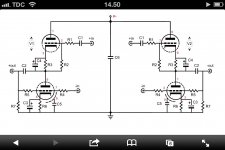
I have been using John Broskies unbalancer as I/V and bal/se converter with the Buffalo dac and thinking I could use the bal/se stage (broskie cathode follower BCF PCB and Kit) of the unbalancer board just to see how it sounds with your I/V. The BCF offers high input impedance - so I can get away with lower value coupling capacitors. I took also snapshot of the schematic and have attached it below. I am only wondering about the input cap on the + signal on the BCF - I guess I don't need that - any of you guys have an idea about that?
By the way - I checked voltage before regulator it was only 52v - so regulator only dropping 7v - but thanks for bringing that up
Attachments
- Home
- Source & Line
- Digital Line Level
- Build Thread - A New Take on the Classic Pass Labs D1 with an ESS Dac