the sets i have left are 50 and 60, no perfect quads left as they all went in the first gb, but they are pretty close to perfect still, go back a decimal and they are. plenty of perfect pairs that are close to each other, which is what i would recommend you go with at this stage, as having highly matched pairs is more important than quads. shipping is either 5aud for regular airmail, or ~20 for registered mail, shoot me an email
Hi Guys,
Glad to see it's moving along well here! I suppose it's time for some Q&A:
CeeVee:
This should be possible to do as I'm sure there are plenty of people who are now buying the BIII. I'll look into it in the next few weeks and report back.
Right now the new GB for "The Wire" headphone and power amps is taking priority, and once everything is done there, I'll sit down and take a look at what can be done with the NTD1.
Davide:
That won't be a problem as long as you short them after the output coupling caps.
That is exactly correct. Those are bleed resistors to keep DC off the output when no load is connected. You'll need to move them off the board and onto the output connector.
Those are for people who want to use electrolytic coupling caps instead of the film ones. For people driving very low impedance loads, it would be impossible to get a large enough value cap on board, so I added the option for electrolytic coupling caps.
No... I would leave it at 100k. The dominant resistance value will likely be whatever you plug it into, and even if you're driving a 10k load, the -3dB point is down at 3.4Hz with a 4.7uF cap. If you're driving a 100k load you're looking at a -3dB point of 0.34Hz.
Regards,
Owen
Glad to see it's moving along well here! I suppose it's time for some Q&A:
CeeVee:
This should be possible to do as I'm sure there are plenty of people who are now buying the BIII. I'll look into it in the next few weeks and report back.
Right now the new GB for "The Wire" headphone and power amps is taking priority, and once everything is done there, I'll sit down and take a look at what can be done with the NTD1.
Davide:
Will it cause any damage to short the output of the D1 ? I am controlling the DAC with the Arduino, and I would like to power up everything, with output shorted and then open them.
That won't be a problem as long as you short them after the output coupling caps.
I will mount the coupling caps off board. I shorted the cap location, I guess I have also to remove R19 R21 etc and put them after the cap, that will be at the output connector.
That is exactly correct. Those are bleed resistors to keep DC off the output when no load is connected. You'll need to move them off the board and onto the output connector.
What are C54 C55 etc for ?
Those are for people who want to use electrolytic coupling caps instead of the film ones. For people driving very low impedance loads, it would be impossible to get a large enough value cap on board, so I added the option for electrolytic coupling caps.
I have 4.7uF coupling caps, does it make sense to increase the bleeder resistor ? How much ?
No... I would leave it at 100k. The dominant resistance value will likely be whatever you plug it into, and even if you're driving a 10k load, the -3dB point is down at 3.4Hz with a 4.7uF cap. If you're driving a 100k load you're looking at a -3dB point of 0.34Hz.
Regards,
Owen
Hi Owen,
Just a comment: Bufallo III does not fit on this board as it is slightly longer then BII.
The connections are at same place so gaining some space at the reg capacitor side would solve problem, maybe you could stretch PCB for this run ?

Owen the next pcb share the same holes than the first one that I have, I said that because I ordered one new BIII so I want to know if I can use the same heatsink that I have using with BII?
I think its just the save pcb, but yes Owen please dont move any devices, if you can move the caps back to allow use with b3 that would be cool for those who plan to use it and use the onboard psu (its meaningless for those who dont plan to) but yes i think its important to keep the same format for the fets etc, otherwise they will have to make an entirely new jig at conrad if anyone wants any sinks.
btw guys, i'm now down to my last 4 sets of fets after 3 have gone, there is still quite a number untested as i stopped after 150, but i wont find any time to do that for a long time, if ever. so those that want them let me know. @merlin that means you =)
btw guys, i'm now down to my last 4 sets of fets after 3 have gone, there is still quite a number untested as i stopped after 150, but i wont find any time to do that for a long time, if ever. so those that want them let me know. @merlin that means you =)
the sets i have left are 50 and 60, no perfect quads left as they all went in the first gb, but they are pretty close to perfect still, go back a decimal and they are. plenty of perfect pairs that are close to each other, which is what i would recommend you go with at this stage, as having highly matched pairs is more important than quads. shipping is either 5aud for regular airmail, or ~20 for registered mail, shoot me an email
I think its just the save pcb, but yes Owen please dont move any devices, if you can move the caps back to allow use with b3 that would be cool for those who plan to use it and use the onboard psu (its meaningless for those who dont plan to) but yes i think its important to keep the same format for the fets etc, otherwise they will have to make an entirely new jig at conrad if anyone wants any sinks.
btw guys, i'm now down to my last 4 sets of fets after 3 have gone, there is still quite a number untested as i stopped after 150, but i wont find any time to do that for a long time, if ever. so those that want them let me know. @merlin that means you =)
80 AUS for four FQA32N20C?
no 60 for the 4 fets, plus either 5 (standard airmail) or 20 (registered mail) depending on what shipping. so 65 or 80 total with shipping depending on which method you choose. considering the amount of work involved, cost for buying extra equipment to get it done, cost for the precision parts and time involved in research and building the difference amp and the amount of unused wasted fets; i think its more than reasonable and i wouldnt do it again at that price, i do better for my normal work, this was just a way of giving back to the community and getting some nice sets; but i didnt plan on giving as much back as i did =) oh well there was some learning in there too, which is always good.
Last edited:
ok cool, i just didnt want to save it for you unnecessarily. i can probably find some that are not matched as well if i went through the numbers again and do for less, but not really that keen to do do more work for less, although it would get rid of some that would stay unused in my parts bin. nobody else has complained about the price I asked a few GB members what they thought was fair given the work involved and stuck to that.
I asked a few GB members what they thought was fair given the work involved and stuck to that.
Last edited:
What's happen if I remove or don't use R19-20-21-23? aren't necessary if the load (BII is connected) right? I ask because the I/V sounded better when connected directly the ouput cap to the connector & jumped the pcb instead to connect the cap at the pcb with the bleed resistors....
Last edited:
Owen the next pcb share the same holes than the first one that I have, I said that because I ordered one new BIII so I want to know if I can use the same heatsink that I have using with BII?
What's happen if I remove or don't use R19-20-21-23? aren't necessary if the load (BII is connected) right? I ask because the I/V sounded better when connected directly the ouput cap to the connector & jumped the pcb instead to connect the cap at the pcb with the bleed resistors....
bump
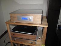
I'm proud of it !!
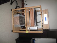
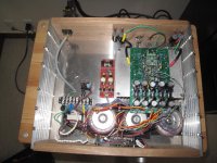
So this is my almost completed D1. I'll still receive the USB-I2S board and I have to fix better the cabling inside and few other things.
I have a slightly modified version of the hifiduino, that allows me to switch on and off the DAC holding the button for more than two seconds. It also shorts the output for switch on and off transient.
On the same rack there are the AD1865, the B1, and on the bottom the F5.
Thanks to all for making this possible.
Merlin, these resistors are bleed resistors for the caps, so that you do not destroy your next stage plugging in the connectors. In reality they should not have any effect.
D.
Attachments
- Status
- This old topic is closed. If you want to reopen this topic, contact a moderator using the "Report Post" button.
- Home
- Source & Line
- Digital Line Level
- A New Take on the Classic Pass Labs D1 with an ESS Dac