Very interesting thread. I plan to buy this kit, but there's 2 version : red PCB and green/blue (unclear) PCB...which one is the new & most updated ? I believe both version support upsampling module, am I right ?
Not sure if this board is available any more, the blue one was the last in the line AFAIK.
Take a look at Sheldons board it will build into a great sounding DAC without needing massive surgery.
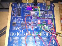
G'loops I have attached a bunch of photographs. I will attempt to explain what I have done.
OK so the power supply rails on the board are shared in a crazy way as standard.
The whole 8416 board is being supplied by a single 3.3v rail with no capacitor decoupling evident.
There is a dedicated 5v supply for the SPDIF toslink socket???
The upsampling board and VA for the CS4398 share a 5v rail.
The USB has a 5v dedicated rail.
The relay has a 12v supply.
Opamps have a bipolar 12v PSU.
I think thats everything.
----------------------------------------------
CS8416
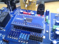
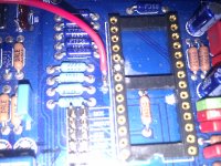
OK I cut traces on both sides of the board under the CS8416 smurf board to isolate VA[3.3v] pin 6. I cut a connecting trace between pin 23 & 21 just outside the socket for the 8416 this isolated VD and VL. Traces on the MAIN BOARD under the smurf board area not actually on the smurf board.
I added 0.01uf X7R caps with 100uf electrolytics directly to the pins of the 8416 smurf board there is a ground pin on the neighbour pins 7 & 23
** note I havnt soldered 2 100uf caps to VD & VL yet.
So 3.3v seperate PSU for pin 6 VA & pin 23VD and 5v on pin 21VL.
The 5v VL PSU is used to power the optical SPDIF and the pullups for selecting the input.
Also put a 47K resistor from VL to pin 20 to change the jitter something as discussed early on in this thread.
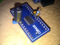
CS8421 board.
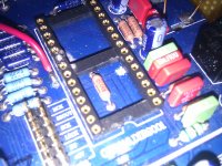
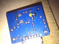
Cut trace next to the CS4398 chip between the 3.3v rails from the SMD regulators, this seperates the 5v VA for the DAC from the CS8421 board.
Added a 0.01uf X7R cap to the supply pin to ground on the CRYSTAL.
Remeoved the regulator and associated input caps and jumped the supply using a copper wire.
Now supplied by a dedicated PSU using LM317 etc.
CS4398 board.
Supplies have all been seperated now so power this up as required with 3.3 volts and 5 volts.
I added 0.01 X7R with 100uf to VD VL and Vref - for Vref there is ground plane just below on the underside of the smurf board use this and solder side on to the board. The CS4398 board is NOT exactly pin for pin like the CS8416 board so be carefull.
*** Vref is pin 15 on the smurf board but its leg 17 on the chip please be warned.
So I think thats it.......
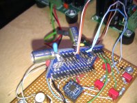
In total I have 6 PSU lm317 to power the chips and a 15v bipolar for my opa627 output board.
I think its best to do this in stages. Seperate the supplies and get rid of all the ferrite beads they suck the life out of the sound.
Phew.......
OK so the power supply rails on the board are shared in a crazy way as standard.
The whole 8416 board is being supplied by a single 3.3v rail with no capacitor decoupling evident.
There is a dedicated 5v supply for the SPDIF toslink socket???
The upsampling board and VA for the CS4398 share a 5v rail.
The USB has a 5v dedicated rail.
The relay has a 12v supply.
Opamps have a bipolar 12v PSU.
I think thats everything.
----------------------------------------------
CS8416
OK I cut traces on both sides of the board under the CS8416 smurf board to isolate VA[3.3v] pin 6. I cut a connecting trace between pin 23 & 21 just outside the socket for the 8416 this isolated VD and VL. Traces on the MAIN BOARD under the smurf board area not actually on the smurf board.
I added 0.01uf X7R caps with 100uf electrolytics directly to the pins of the 8416 smurf board there is a ground pin on the neighbour pins 7 & 23
** note I havnt soldered 2 100uf caps to VD & VL yet.
So 3.3v seperate PSU for pin 6 VA & pin 23VD and 5v on pin 21VL.
The 5v VL PSU is used to power the optical SPDIF and the pullups for selecting the input.
Also put a 47K resistor from VL to pin 20 to change the jitter something as discussed early on in this thread.
CS8421 board.
Cut trace next to the CS4398 chip between the 3.3v rails from the SMD regulators, this seperates the 5v VA for the DAC from the CS8421 board.
Added a 0.01uf X7R cap to the supply pin to ground on the CRYSTAL.
Remeoved the regulator and associated input caps and jumped the supply using a copper wire.
Now supplied by a dedicated PSU using LM317 etc.
CS4398 board.
Supplies have all been seperated now so power this up as required with 3.3 volts and 5 volts.
I added 0.01 X7R with 100uf to VD VL and Vref - for Vref there is ground plane just below on the underside of the smurf board use this and solder side on to the board. The CS4398 board is NOT exactly pin for pin like the CS8416 board so be carefull.
*** Vref is pin 15 on the smurf board but its leg 17 on the chip please be warned.
So I think thats it.......
In total I have 6 PSU lm317 to power the chips and a 15v bipolar for my opa627 output board.
I think its best to do this in stages. Seperate the supplies and get rid of all the ferrite beads they suck the life out of the sound.
Phew.......
Attachments
-
 IMAG0111.jpg860.2 KB · Views: 754
 -
 IMAG0122.jpg853.6 KB · Views: 704
 -
 IMAG0124.jpg385.5 KB · Views: 628
 -
 IMAG0112.jpg616.4 KB · Views: 605
 -
 IMAG0121.jpg827.6 KB · Views: 593
 -
 IMAG0123.jpg956.4 KB · Views: 168
 -
 IMAG0125.jpg736.3 KB · Views: 150
 -
 IMAG0126.jpg809.6 KB · Views: 176
 -
 IMAG0128.jpg897.6 KB · Views: 212
 -
 IMAG0127.jpg446.4 KB · Views: 205
Last edited:
Can anyone help me understand how to find out what the input impedence of a given filter network would be? eg I am using the CS AN048 multiple feedback filter with a roll at aprox 50Khz.
I want to raise the cut off Fc to aprox 100Khz. This changes the resistor values, what is the resulting input impedance???
I used this utility Multiple Feedback Low-pass Filter Design Tool
CS AN048 values are 13.7K and 3.32K so is the input impedance aprox 13.7K the first resistor?
And so if I have values of
[SIZE=-1][SIZE=-1]R1 = 3.3kΩ
R2 = 3.6kΩ
R3 = 3.3kΩ
C1 = 0.001uF
C2 = 220pF[/SIZE][/SIZE]
using the utility above I get Fc of aprox 100Khz
Do I have an input impedance of aprox 3.3K......this would be OK for the CS4398 to drive; according to the datasheet?
I studied Mech. Eng and not electrical so on a steep learning curve. Trying to dodge the enevitable fact that I will have to hit the books to re-apply earlier learning....its all a bit similar to Dynamics and Control lots of laplace & Z transforms and matrices thrown in for good measure.
Help me dodge this bullet....
And if you get rid of the opamps and install a pair of OPT you get to hear theIn total I have 6 PSU lm317 to power the chips and a 15v bipolar for my opa627 output board.
CS4398´s potential..
")
Hi Risen,
At some point I will try using Trafo's, I am fully aware of the massive following they have in this thread. I am also curious to hear what they sound like, I have an open mind on the subject.
I have concentrated on the source of the signal going into the output stage working on the "Rubbish In Rubbish Out" principal. Its easy to fall into the trap of concentrating on the glamerous stuff.
I and others have carried out a fair bit of work on this area and it will benifit both opamp and transformer. A good and fast opamp is very good at revealing a poor signal source even if it sounds "electronic" to some ears. Transformer might sound better subjectively to some ears.
You can put a Transformer on the output and leave it at that however you are not even hearing 50% of the boards capability if this is the only thing you do.
George.
I have tried many opams and I allways end up with the LM4562 as being the best sounuding,and the thing about rubbish in rubbish out if you put a trafo instead of the opamp,then you hear what was making the rubbish..
I have 4 shuntregs on the DAC and other various tweaks,so let hope they make things better for the DAC.
I have 4 shuntregs on the DAC and other various tweaks,so let hope they make things better for the DAC.
Ryssen, an interesting point you raise is that you like the LM4562. I think its a very good opamp. When I first listened to it I was very pleased with the SQ it was very impactfull and had good pace........etc etc all subjective stuff.
On closer examination of the sound based on vocals sibilance transparency etc [more analytical listening but still subjective I suppose] OPA627 was ahead, however overall LM4562 was still more pleasing to listen to, why?
As the upgrades were made and I kept swapping between NE5532 OPA627 & LM4562 I realised what was happening.
The OPA627 is definately the most revealing out of all the above OPAMPS and for this reason it is the hardest to get a good sound from.
Its only now after all theses mods that I have been able to get the OPA627 to perform. Now when I put the the other OPAMPS in I lose the magic, the detail, not much detail in the case of the 4562 more with the NE5532 gets lost along with transparency and dynamics.
I found placing a 600 ohm resistor in series on the output of the 627 and decopling supply rails properly is essential for fast high bandwidth OPAMPS.
If you are making PSU upgrades its not enough to just change the existing LM317 to better regulator designs. It will improve the SQ for sure, but its limited. There are fundamental design flaws with the power distribution on this board.
The best and most fundamental SQ improvement is only obtained when the supply rails are seperated properly and the VL on the 8416 is raised to 5v. Get rid of the ferrites! Add decoupling and you enter another world.
At some point I will try using Trafo's, I am fully aware of the massive following they have in this thread. I am also curious to hear what they sound like, I have an open mind on the subject.
I was skeptical at first as well, and I was in the middle of a design using the same chips, so I added a set of Lundahl outputs to the design, and I'm amazed at how natural and lifelike they sound. And I'm not a transformer coupling guy at all.
Also the ground plane is as much or more important than the power supplies. I use 7 discrete power supplies just for the three chips on my design. And the chips are down on the ground plane.
Sheldon
Hi Sheldon,
I am familiar with your board and I like it. IMHO its correctly designed to extract the best from this trio of chips. The work I am doing with the Gigaworks is simply bringing the design closer to your board.
I will try the transformer output, I just stopped work on the output stage altogether when I realised how much performance was locked away in the chips!!
When I feel that I have experimented and squeezed [or break] the best from the chips I will look at the output stage again, Trafo's and OPAMP filters.
Hi Ryssen, I must point out that removing the FB's is probably a waste of time if you dont seperate the supply rails. Its probably why you dont hear any difference .
If you do seperate the supplies there is an FB on the 8421 board that chokes the sound.
Talking of the 8421 board I will need to add yet another PSU to run at 2.5v as the 8421 chip requires 2 power rails. This will bring the PSU count to 7 excl opamp supply, the same as sheldons board.
The work never ends....
Do you mean that every PSU needs its own winding (transformer)The work never ends....
Or is a preregulator enough?
Do you mean that the 8421 VD and VL needs separate PSU?
I a separate regulator for the XO now.
Currently the upsampling board has a single 3.3v regulator situated on the board, its fed from a 5V rail. On the standard board the 5V rail is shared by VA on cs4398 DAC. There is a FB on the upsampling board which is used to isolate the supply, its shared remember.
On my modified board I have cut the track and provided the upsampling board with a dedicated supply at 3.3V. I also removed the FB and associated input caps. Take a look at the pictures in my earlier post.
I have 3 transformers which gives me 6 seperate windings each with its own regulated PSU. [overkill, but makes a difference]
Now here is the issue:
The 8421 needs 5.0V/3.3V for VL and 2.5V for VD and I have 3.3V on both, in an ideal world I would run VL at 5V and use a seperate regulator at 3.3V for the clock with another at 2.5V for VD. In total I need 3 regulated supplies, I need to add another 2. I will get round to it at some point. I will share a couple of the transormer windings to do this by adding fully rectified PSU.
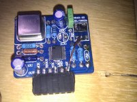
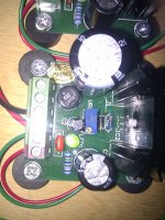
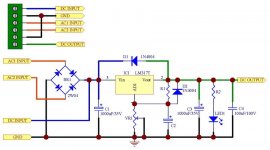
I buy these power supplies, fully rectified variable LM317, I change the smoothing caps to 4700uf.
Voltage Regulator Kit, AC/DC in, DC out, Based on LM317 | eBay
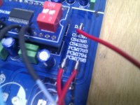
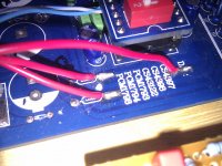
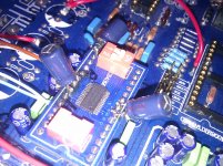
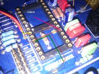
I have included a photograph of where to look for the shared track its the middle one between the tracks. If you lift the DAC out and follow these tracks you will see how the supplies are all mixed up.
I cant express the difference it makes to seperate them, even if you dont add seperate transformer windings.
Voltage Regulator Kit, AC/DC in, DC out, Based on LM317 | eBay
I have included a photograph of where to look for the shared track its the middle one between the tracks. If you lift the DAC out and follow these tracks you will see how the supplies are all mixed up.
I cant express the difference it makes to seperate them, even if you dont add seperate transformer windings.
Attachments

Last edited:
The 8421 needs 5.0V/3.3V for VL and 2.5V for VD and I have 3.3V on both, in an ideal world I would run VL at 5V and use a seperate regulator at 3.3V for the clock with another at 2.5V for VD. In total I need 3 regulated supplies, I need to add another 2. I will get round to it at some point. I will share a couple of the transormer windings to do this by adding fully rectified PSU.
I pointed out the problem with the design back many pages ago, that they were running the 2.5V VD at 3.3 volts (really really close to the absolute maximum rating). Apparently the chips can handle it, but it's not a good idea. Back toward the beginning of this thread there were a bunch of folks who were toasting 8421's and I found that issue with the design. I haven't heard of anyone having issues lately, so apparently the 3.3 volt regulator on the newer ASRC board does the trick.
Sheldon
Yup I read the same stuff earlier in the thread, initially I assumed my board was newer and the issue was completely fixed. I initially thought the on-board reg was 2.5V and maybe the rail voltage was 3.3V.
This is not the case, I wonder if there is a potential divider dropping the voltage? Just not sure. I will get to the bottom of it at some point.
The whole board is a mess.
Its working out to be a great tutorial, learning all the way.
Finally I am getting what I would consider as "high fidelity" sound. Its starting to remind me of my past equipment.
Can you point out to me what each of the wires in the first pic are, I take it the red ones are coming from the ebay regs? supplying X.Xv?I buy these power supplies, fully rectified variable LM317, I change the smoothing caps to 4700uf.
Voltage Regulator Kit, AC/DC in, DC out, Based on LM317 | eBay
I have included a photograph of where to look for the shared track its the middle one between the tracks. If you lift the DAC out and follow these tracks you will see how the supplies are all mixed up.
I cant express the difference it makes to seperate them, even if you dont add seperate transformer windings.
What about the other two under that go under the DAC daughter board?
Thanks
I'm only now looking at doing more than the transformer output.
- Home
- Source & Line
- Digital Line Level
- Experience with this DIY DAC ?