robert1325 said:How would the Trend go with some Hawthorne SI's?
I think they would make a great match.
The guy who got the 1st modded TA-10, Shep, was looking at the Silver Iris stuff.. I tried my best to talk him into it, but he went with the Crafty Speakers from your part of the world. He likes them!
It Lives!!
Luckily I managed to get the smoke back in where it belonged!!")
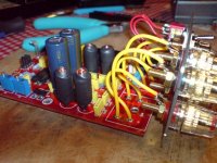
I took a good look at the TA-10 and (tada!) it is now repaired. One burnt resistor (although it still showed the correct resistance) and some further checking with my DMM revealed a poor earth and poor connections on one pot channel where I had replaced parts. Shame on me for poor workmanship - serves me right for rushing!! A work of warning when working on these double sided boards, I suppose, as I did not pay too much attention to where the tracks ran above and below the board when I was getting a nice solder joint - best let that solder flow through the holes and make a decent connection on BOTH sides of the PCB! Once those were sorted out, we were back in business and I did put in the 2200uF panaFC tank caps to replace the 220uF ones in there. I can’t remember what it sounded like before to see if there is any major difference, but I can tell you that I am very impressed by this little amp. Lucky the Tripath chip has all those built in protections for bodgers like me!! The quality of the sound of this amp has definitely grabbed my attention and I'm enjoying it all the more seeing as it cost less than 60 UKP!!
I replaced the RCAs (and want to do the binding posts as well sometime), tank caps, power switch and internal wiring. I'd prefer to tidy up some of the soldering inside too, but you might argue that I should stop whining and buy a kit!! Trends has done a good job here - perhaps they might consider an SE version with some higher quality plugs etc. Overall, this is 6+/10 for build quality, 8+/10 for sound, and 12++/10 for value.
Cheers
Jon
I let some smoke escape!!!

Luckily I managed to get the smoke back in where it belonged!!
I took a good look at the TA-10 and (tada!) it is now repaired. One burnt resistor (although it still showed the correct resistance) and some further checking with my DMM revealed a poor earth and poor connections on one pot channel where I had replaced parts. Shame on me for poor workmanship - serves me right for rushing!! A work of warning when working on these double sided boards, I suppose, as I did not pay too much attention to where the tracks ran above and below the board when I was getting a nice solder joint - best let that solder flow through the holes and make a decent connection on BOTH sides of the PCB!
Once those were sorted out, we were back in business and I did put in the 2200uF panaFC tank caps to replace the 220uF ones in there. I can’t remember what it sounded like before to see if there is any major difference, but I can tell you that I am very impressed by this little amp. Lucky the Tripath chip has all those built in protections for bodgers like me!! The quality of the sound of this amp has definitely grabbed my attention and I'm enjoying it all the more seeing as it cost less than 60 UKP!!I replaced the RCAs (and want to do the binding posts as well sometime), tank caps, power switch and internal wiring. I'd prefer to tidy up some of the soldering inside too, but you might argue that I should stop whining and buy a kit!!
Trends has done a good job here - perhaps they might consider an SE version with some higher quality plugs etc. Overall, this is 6+/10 for build quality, 8+/10 for sound, and 12++/10 for value.Cheers
Jon
Attachments
Well, can you believe that I waited over a little over a week since I received it before I even powered it up and listened to it ? My speakers only came yesterday. The sound is amazing with that large sound stage effect, but when I opened it up, I was a little disappointed with the poor workmanship that was inside. I see solderballs all around the PCB and on some components, wire soldering was terrible and the air core inductors were bent sideways, the solder joint of the Tripath chip was not proberly wetted so I had to resolder one the big joints with my elcheapo soldering pen, ( I see two shorts on the leads, I don't know if that is intentional or what, anyone else see that ?, if you do then it is) so I just prettied everything up and retouched some of the solder joints and spent some time mopping your the dirty PCB with solvent and Q-Tip to get rid of all those solder balls and flux residue that can short and impede current.
Soldering on the bottom side or solder side should be sufficeint for through-hole parts, solder will wick its way up to the top side or solder destination side. A 75% fill of the barrel is considered acceptable.
Trying applying a sheet of tacky film or clear tape on the bottom side to avoid shorting.
Once my new Hakko soldering station arrives, I will replace all the wiring with teflon wires and take out the whole board and dip it into a bath of isopro achol to make everything more asthecally pleasing.
I agree with: 6/10 for build quality, 8+/10 for sound, and 11/10 for value ...LoL
What else is a worthwhile upgrade ? give me specifics and values of the components.
I did warn you guys that the build quality leave something to be desired....
Jon, glad to hear you got it back up and running. You're going to enjoy the little guy, for sure.
May I suggest - http://www.michael.mardis.com/trendamp/ta-10.htm
Jon, glad to hear you got it back up and running. You're going to enjoy the little guy, for sure.
EdT said:What else is a worthwhile upgrade ? give me specifics and values of the components.
May I suggest - http://www.michael.mardis.com/trendamp/ta-10.htm
The Charlize has a TA2020 chip inside. I have listened briefly to an unmodified Sonic Impact T-amp which has the TA2024 chip inside and after that I was happy to have chosen the TA2020 chip for my T-amp. Comparing the sound of the two was a bit difficult because the input cap of the SI was original. Apart from the lack of bass in the SI I could not hear important differences in the way the two amps perform. I think the extra power in the TA2020 makes it more versatile.robert1325 said:has anyone compared it to the Charlize?
Should have gone that route right away
I'm seriously thinking of getting some Hawthorne SI's , they seem a very good match with T-amps.
I use a pair of Jordan JX92S fullrange speakers (Konus Essence clone) with my TA2020.
I'm a big fan of the 2020 chip, too. Very musical.
The TA2020 has a few other advantages.
1) It can run at a higher voltage than the TA2024 - so a little more power.
I run them at 14.6V no problem. With good heatsinking the chip never gets warm, even into a 4 Ohm load. I would guess that 15V should be no problem.
2) For whatever reason, the TA2020 seems to get closer to power rail voltage before clipping than its smaller brothers. The TA2020 can get to within 1V of the rails, the others seem to never get closer than 2V. That helps power.
The on chip Tripath amps I've heard sound a lot alike - no surprise - but I do like the TA2020 best.
No monobloc!
Yes, one amp per speaker. Since posting this question, I read, I think it was on Panomaniac's site, that such a monobloc arrangement is not possible with T amps because they are already bridged.
I know little about the circuit design, building, etc., so I need to rely on others. Anyhow, I did see the process of "stapling" jumpers on the Trends unit mentioned and wonder if that would be applicable for using one amp per channel.
panomaniac said:What do you mean by monoblock? Two amps, one for each speaker?
Yes, one amp per speaker. Since posting this question, I read, I think it was on Panomaniac's site, that such a monobloc arrangement is not possible with T amps because they are already bridged.
I know little about the circuit design, building, etc., so I need to rely on others. Anyhow, I did see the process of "stapling" jumpers on the Trends unit mentioned and wonder if that would be applicable for using one amp per channel.
Rewiring and Cleaning Up TA-10
I finally got a chance to redo the wiring and clean-up the top and bottom side of the PCB. I was fortunate enough to find some 18 AWG tin copper Teflon wires at a local electronic surplus store and it even came in yellow like the original wires. They had no idea what they were selling to me cause Teflon wire is usually big$$$ !
Here is how my TA-10 amp looked like once it was opened. Notice the hideous soldering workmanship of the wiring. The jacket material is melted into the solder cups and terminals and there is no gap between the wire jacket and the soldering joints. Another thing I noticed was that there was barely any wire in the soldering cup and only 2-3mm that was tacked onto the cup. Another thing I noticed was that two different type of wires gauge was use, 20 AWG(orange) for the RCA jacks and 18 AWG(yellow) for the speaker jacks. The reason I found later on was the drill holes on the PCB can only accomandate 20AWG for the RCA jacks, a little too small for my liking as an input signal. I was able to insert 18 AWG wire very snuggly into the RCA drill holes once I cleaned out the solder with solder wick and compressed air . Yay, I can now used 18 gaguge for the input signal !
Top view after redoing the wiring, I also added a custom fitted heatsink on top of the Tripath chip, don't know if it get warm, but anyways I had one lying around.
Front end view of the rewiring
Notice the required gap(Diameter of the core wire) of the jacket material and the solder joint on the PCB and the solder terminals and cups. You will also noticed that there is no fraying of the jacket material due to melting, but then again using Teflon eliminates that problem that is common on PVC insulations.
The wire must be strip to a length that it touches the bottom of the cup once it is inserted plus enough for the required gap between the solder joint and the wire insulation. The original solder joint only had about 2-3mm of wire inserted and worse the cup was not properly filled with solder leaving air pocket in the solder cup with only the lip of the cup having any contact with the wire. Notice the proper way to fill a solder cup, you will see a concave wetting fillet of solder and the strands of the wire is still discernable. This is the proper way to fill a solder cup, it is Mil spec and NASA standards used in mission critical applications !
Another shot of the soldering cup for the right RCA jack
After soldering clean off all flux residue with achool and a cotton swab and the solder joints should look all shiny like jewellery !
I finally got a chance to redo the wiring and clean-up the top and bottom side of the PCB. I was fortunate enough to find some 18 AWG tin copper Teflon wires at a local electronic surplus store and it even came in yellow like the original wires. They had no idea what they were selling to me cause Teflon wire is usually big$$$ !
Here is how my TA-10 amp looked like once it was opened. Notice the hideous soldering workmanship of the wiring. The jacket material is melted into the solder cups and terminals and there is no gap between the wire jacket and the soldering joints. Another thing I noticed was that there was barely any wire in the soldering cup and only 2-3mm that was tacked onto the cup. Another thing I noticed was that two different type of wires gauge was use, 20 AWG(orange) for the RCA jacks and 18 AWG(yellow) for the speaker jacks. The reason I found later on was the drill holes on the PCB can only accomandate 20AWG for the RCA jacks, a little too small for my liking as an input signal. I was able to insert 18 AWG wire very snuggly into the RCA drill holes once I cleaned out the solder with solder wick and compressed air . Yay, I can now used 18 gaguge for the input signal !
An externally hosted image should be here but it was not working when we last tested it.
Top view after redoing the wiring, I also added a custom fitted heatsink on top of the Tripath chip, don't know if it get warm, but anyways I had one lying around.
An externally hosted image should be here but it was not working when we last tested it.
Front end view of the rewiring
An externally hosted image should be here but it was not working when we last tested it.
Notice the required gap(Diameter of the core wire) of the jacket material and the solder joint on the PCB and the solder terminals and cups. You will also noticed that there is no fraying of the jacket material due to melting, but then again using Teflon eliminates that problem that is common on PVC insulations.
An externally hosted image should be here but it was not working when we last tested it.
The wire must be strip to a length that it touches the bottom of the cup once it is inserted plus enough for the required gap between the solder joint and the wire insulation. The original solder joint only had about 2-3mm of wire inserted and worse the cup was not properly filled with solder leaving air pocket in the solder cup with only the lip of the cup having any contact with the wire. Notice the proper way to fill a solder cup, you will see a concave wetting fillet of solder and the strands of the wire is still discernable. This is the proper way to fill a solder cup, it is Mil spec and NASA standards used in mission critical applications !
An externally hosted image should be here but it was not working when we last tested it.
Another shot of the soldering cup for the right RCA jack
An externally hosted image should be here but it was not working when we last tested it.
After soldering clean off all flux residue with achool and a cotton swab and the solder joints should look all shiny like jewellery !
An externally hosted image should be here but it was not working when we last tested it.
I also notice now that there is now a white component on the power jack that was not on earlier TA-10 builds. Anyone know what it does ?
An externally hosted image should be here but it was not working when we last tested it.
windowlicker said:Yesterday I have received my Trends Audio amplifier that, according to the front, is a 'Class-T Amplifier TA-10.1'
Is anyone aware of the .1 version and what the difference is with the original TA-10?
No idea, fire an email to David at Trends Audio for an answer.
Listening comparisons.....
Hi Everyone,
Been listening to the Arcam D290Ps in stereo biamp config. Although there is more power available (2 x 70 WPC), I think I prefer the detail of the TA-10!!! I'll continue listening for a few more days......
Going to visit the big boys this weekend. I'll be bringing the TA-10 along to compare with a Krell (can't remember which integrated model it is) and to run in a very high end sysyem (if they let me!! ). I'll report back!
Cheers
Jon
ISTR there is a 100 WPC Tripath amp. I might be tempted to give it a try while I'm waiting for my Aleph X kits to build themselves!!
Hi Everyone,
Been listening to the Arcam D290Ps in stereo biamp config. Although there is more power available (2 x 70 WPC), I think I prefer the detail of the TA-10!!!
I'll continue listening for a few more days......Going to visit the big boys this weekend. I'll be bringing the TA-10 along to compare with a Krell (can't remember which integrated model it is) and to run in a very high end sysyem (if they let me!!
). I'll report back!Cheers
Jon
ISTR there is a 100 WPC Tripath amp. I might be tempted to give it a try while I'm waiting for my Aleph X kits to build themselves!!
- Status
- This old topic is closed. If you want to reopen this topic, contact a moderator using the "Report Post" button.
- Home
- Amplifiers
- Class D
- Trends Audio TA-10: Modding Potential?