A long time in the works, the Ref-T is my version of a Tripath based amplifier.
The board is designed around the TA2021B which is the "slug up" version of the TA2024, meaning the chip's heat slug is facing upwards enabling you to attach a heat sink to it for better heat dissipation.
The Ref-T has the same features as all the other TA2020/1B/4 variants plus a little bit extra.
First, there is room for on board surface mount or radial input coupling caps. There are also large enough holes to allow you to directly connect the leads of larger off board caps if you'd want to do so.
There is a DC offset nulling adjustment added to each channel at the input so you can zero the DC offset at each output by adjusting a potentiometer.
There is a soft start circuit that can be jumpered to the mute pin to keep the outputs muted while the input coupling caps charge for a set amount of time, thus avoiding the dreaded turn-on thump. You may also jumper the mute pin to ground to keep the amp unmuted at all times. There is a jumper for the sleep pin as well. You can jumper it to ground to keep the amp awake all the time, or you can wire up a switch to put the amp into low power sleep mode when you choose.
There are two status LEDs. One indicates when the inputs are being overdriven and the other indicates when the internal fault protection circuitry has been tripped.
There is ample space on the board for your choice of output inductors - ferrite bobbin core, toroidal, aircore, etc. The footprint for the output filter caps can accept 5mm, 7.5mm, and 10mm spacing radial film caps.
The major difference between this board and others is in the implementation of the power supply. There are 4 separate external regulators for the various supply inputs on the chip. One TO220 size regulator for the output stages of each channel, one TO220 size regulator for the analog driving stage, and one SOT223 size regulator for the 5V input section. Interestingly enough, Tripath was kind enough to let me know that certain supply pins are "weakly" connected internally, so large voltage differentials between the supply pins could result in current flowing through the weak connections and having them blow like a fuse. This could damage the chip but I'm going to build one up anyway and see what happens! My gut feeling tells me that nothing will happen if I use quality regulators and the output voltages are set very close to one another.
In light of this bit of information, I have a second version of the Ref-T layout all but finished that uses one regulator for the high voltage pins (12-14V) and another regulator for the 5V pins. The board is also smaller since less components are used.
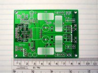
Enough chat, here are a couple photos of the board.
This one is the top side.
The board is designed around the TA2021B which is the "slug up" version of the TA2024, meaning the chip's heat slug is facing upwards enabling you to attach a heat sink to it for better heat dissipation.
The Ref-T has the same features as all the other TA2020/1B/4 variants plus a little bit extra.
First, there is room for on board surface mount or radial input coupling caps. There are also large enough holes to allow you to directly connect the leads of larger off board caps if you'd want to do so.
There is a DC offset nulling adjustment added to each channel at the input so you can zero the DC offset at each output by adjusting a potentiometer.
There is a soft start circuit that can be jumpered to the mute pin to keep the outputs muted while the input coupling caps charge for a set amount of time, thus avoiding the dreaded turn-on thump. You may also jumper the mute pin to ground to keep the amp unmuted at all times. There is a jumper for the sleep pin as well. You can jumper it to ground to keep the amp awake all the time, or you can wire up a switch to put the amp into low power sleep mode when you choose.
There are two status LEDs. One indicates when the inputs are being overdriven and the other indicates when the internal fault protection circuitry has been tripped.
There is ample space on the board for your choice of output inductors - ferrite bobbin core, toroidal, aircore, etc. The footprint for the output filter caps can accept 5mm, 7.5mm, and 10mm spacing radial film caps.
The major difference between this board and others is in the implementation of the power supply. There are 4 separate external regulators for the various supply inputs on the chip. One TO220 size regulator for the output stages of each channel, one TO220 size regulator for the analog driving stage, and one SOT223 size regulator for the 5V input section. Interestingly enough, Tripath was kind enough to let me know that certain supply pins are "weakly" connected internally, so large voltage differentials between the supply pins could result in current flowing through the weak connections and having them blow like a fuse. This could damage the chip but I'm going to build one up anyway and see what happens! My gut feeling tells me that nothing will happen if I use quality regulators and the output voltages are set very close to one another.
In light of this bit of information, I have a second version of the Ref-T layout all but finished that uses one regulator for the high voltage pins (12-14V) and another regulator for the 5V pins. The board is also smaller since less components are used.
Enough chat, here are a couple photos of the board.
This one is the top side.
Attachments

Very nice work BWRX.
Thats kind of like asking children if they would interested in a bowl of ice cream.
I think the better question is, what would be a reasonable price for such a kit?
Would anyone be interested in an amp like this - as a kit or an assembled amp?
Thats kind of like asking children if they would interested in a bowl of ice cream.
I think the better question is, what would be a reasonable price for such a kit?
BWRX, looks great. I was just thinking, "Geez, these little Tripath modules would sound even better if a separate 5V supply was added. Now, how would I do that?" Seems the answer is to buy a board from BWRX, if he puts one out. I'd also want to use better than mylar output capacitors, and Vishay bulk foil smd resistors (I know, I know, ridiculous, but hey) ....
theAnonymous1 said:Very nice work BWRX.
Thats kind of like asking children if they would interested in a bowl of ice cream.
I think the better question is, what would be a reasonable price for such a kit?
Amen!!!
Joe
Good job!
Brian,
Whether people will be interested or not depends on 3 things, price, price and price!
Nice symmetric layout, large ground areas, good job. I have no criticism till I actually try and build one. It probably would be best supplied with the 2021 installed. This would be the place I would think most errors would occur.
For most DIY’ers the problem sourcing things like a nice metal case and matching knobs is a problem. If you could offer these things it would make the overall project more attractive. I have a source in Taiwan that will make cases to spec and from the quality and looks I have seen this might be a source for you to consider. Here’s a link;
http://www.atiresearch-anodized.com/ I am using the one shown in the center and it is very nice! If you do go this way you should offer a SMPS that will fit in the same case. Many sources for this but the new offering from Digikey looks particularly attractive. Links;
http://www.cui.com/adtemplate_child...catky=764537&subcatky1=46887&subcatky2=809398
http://www.digikey.com/scripts/dksearch/dksus.dll?KeywordSearch?MPart=VOF-45-12&site=us
Note the very attractive price and 2’ X 4” foot print!
Let us know when you have one stuffed and working. Also let us know when you figure out what you have to get for the boards.
Roger
Thanks for the replies guys.
I'm hoping a good low noise 5V regulator helps expose some hidden potential as well! Mylar output caps eh... My plan was to go with some nice polypropylene or polyester film caps since they're not too expensive and are great for the intended purpose. All the surface mount footprints are 0805 and larger but you can easily fit 0603 parts on the 0805 footprint I used for the board. It's all about flexibility.
So I guess price is the deciding factor then?")
I still have to get a few more parts before I can get one up and running. In the meantime I'm working on coming up with a reasonable price for a kit, probably with an option to have the chip already soldered to the board.
I would love to be able to offer a complete amp but I simply don't have the time to do so right now. Those ATI cases are very attractive though! Especially that pair of matching cases that seems like it would be a good size to house the amp in one and the supply in the other...
Roger brought up using a switching supply (and those are some nice looking modues in the links), which reminds me to say that you don't have to use the linear regulators. You can just wire any supply right to the through hole output pads of the linear regulators. I would still use a good low noise linear regulator for the 5V section. It would even be possible to use a battery for complete isolation from the output power supply. That's something I'll have to ecperiment with.
I'll definitely post updates as things start moving along. This weekend will be a good opportunity to get something done since it's a 3 day weekend (you have to love Good Friday).
I'm hoping a good low noise 5V regulator helps expose some hidden potential as well! Mylar output caps eh... My plan was to go with some nice polypropylene or polyester film caps since they're not too expensive and are great for the intended purpose. All the surface mount footprints are 0805 and larger but you can easily fit 0603 parts on the 0805 footprint I used for the board. It's all about flexibility.
So I guess price is the deciding factor then?
I still have to get a few more parts before I can get one up and running. In the meantime I'm working on coming up with a reasonable price for a kit, probably with an option to have the chip already soldered to the board.
I would love to be able to offer a complete amp but I simply don't have the time to do so right now. Those ATI cases are very attractive though! Especially that pair of matching cases that seems like it would be a good size to house the amp in one and the supply in the other...
Roger brought up using a switching supply (and those are some nice looking modues in the links), which reminds me to say that you don't have to use the linear regulators. You can just wire any supply right to the through hole output pads of the linear regulators. I would still use a good low noise linear regulator for the 5V section. It would even be possible to use a battery for complete isolation from the output power supply. That's something I'll have to ecperiment with.
I'll definitely post updates as things start moving along. This weekend will be a good opportunity to get something done since it's a 3 day weekend (you have to love Good Friday).
The board looks nice, Brian.
I got a quote on assembling the SMD part by machine, I'll contact you with details.
Offering the kit with 3 options might be nice, depending on how much hassle it is for you.
1) PCB and parts. User builds everything. (41Hz style)
2) PCB with all SMD parts in place. (That's what I would like)
3) Kit fully assembled. (Charlize style).
Not to worry about the fully built amps. You know if it sounds as good or better than the AMP6 I'll be putting them in my Octopus Amps. Right now the 2020 chip is sounding mighty good, going to be hard to beat!
sx881663 - Thanks for the reminder on the Thailand case company, nice stuff. ( World's slowest loading web page, tho. Been meaning to bug them about that.)
Brian, yes, mylar's evil and polypropylene's much preferred. Mylar (polyester) is polar and performs some nice distortion tricks in any circuit in which it finds itself.
On the topic of evil, X5Rs are eviller than mylar: down there in the dumps with electrolytics. C0Gs are great.
On the topic of evil, X5Rs are eviller than mylar: down there in the dumps with electrolytics. C0Gs are great.
BWRX said:Michael, that information would be very helpful to know!
I sent it to you by email. Machine assembly isn't cheap, but niehter is your time. =) Like everything else, it pays to shop around.
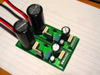
I haven't started to populate the Ref-T board yet (although I do have enough parts to get one up and running... I think), but I did build my regulated supply today. I made this board as well.
The LDO linear regulators are the inimitable LT1085 from Linear Tech. The input and output caps are 3900uF and 680uF Nichicon HEs bypassed by 0.015uF polypropylene film caps.
I designed the board to have three sets of outputs so I could jumper one regulator to each of the three 14V supply inputs on the Ref-T board in case my independent supply idea doesn't work. Pretty slick, huh?
Attachments
panomaniac said:2) PCB with all SMD parts in place. (That's what I would like)
Me too.
dave
Micheal gave me a couple links to places that can do assembly. It costs more for through hole and fine pitch SMT parts. If I can get the boards made with all the small surface mount parts done I can put the chips and the through hole parts on myself and probably save a bit on the overall cost. I haven't had time to get a detailed quote just yet as I haven't even built the current boards! The iron is fired up and ready to go though. Time to head down to the workshop 
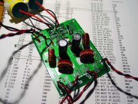
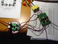
She's alive! It makes music and it sounds quite nice. It's rather noisy though for a couple reasons. Reason one, the signal and speaker outputs are connected by alligator clips (albeit silver stranded audiophile quality ones ). Reason two, I have wires everywhere and the setup is next to my computer and halogen lamp. Reason three, there are no caps in the output filter! It's running with only the inductors. I took them in to work today and measured them and they are 13uH at 100kHz with 41 turns on the toroid core. They're the same inductors supplied with the amp3 and amp6 kits from 41hz.
Regardless, it sounds nice with a wallwart for the unregulated input to the Vdd regulator and a 9V battery before the 5V regulator (that might be another reason why it's rather noisy). I can tell channel separation is already a bit better as the imaging is very good.
). Reason two, I have wires everywhere and the setup is next to my computer and halogen lamp. Reason three, there are no caps in the output filter! It's running with only the inductors. I took them in to work today and measured them and they are 13uH at 100kHz with 41 turns on the toroid core. They're the same inductors supplied with the amp3 and amp6 kits from 41hz.Regardless, it sounds nice with a wallwart for the unregulated input to the Vdd regulator and a 9V battery before the 5V regulator (that might be another reason why it's rather noisy). I can tell channel separation is already a bit better as the imaging is very good.
Attachments
- Status
- This old topic is closed. If you want to reopen this topic, contact a moderator using the "Report Post" button.
- Home
- Amplifiers
- Class D
- My Ref-T amp