BWRX said:She's alive! Regardless, it sounds nice with a wallwart for the unregulated input to the Vdd regulator and a 9V battery before the 5V regulator,I can tell channel separation is already a bit better as the imaging is very good.
Brian,
The more you tell us the more intriguing this sounds,yes I'm interested - you betcha !
A little bit of info about an incident I had involving that 9V battery...
As it turns out, the Tripath chip does not like it when the 5V supply drops to around 3V... I was listening and the amp just started reproducing white noise that gradually rose in volume until I jumped out of my seat and unplugged power. Moral of the story, the analog input section needs a nice steady 5V") Since then I've hooked up another regulator to for the 5V section and there is definitely a bit of improvement in the sound. Not to mention the bass! Holy cow, I used 820uF 35V Nichicon HEs right next to the chip and there is absolutely no lack of bass whatsoever. My speakers are playing low notes I haven't heard them reproduce before! Almost sounds overpowering but I'm not used to much bass at all since my speakers are only 2 ways with a 1in tweet and 6.5in mid driver. Interestingly enough, the highs don't seem to have been reduced even though the bass is definitely more substantial.
Since then I've hooked up another regulator to for the 5V section and there is definitely a bit of improvement in the sound. Not to mention the bass! Holy cow, I used 820uF 35V Nichicon HEs right next to the chip and there is absolutely no lack of bass whatsoever. My speakers are playing low notes I haven't heard them reproduce before! Almost sounds overpowering but I'm not used to much bass at all since my speakers are only 2 ways with a 1in tweet and 6.5in mid driver. Interestingly enough, the highs don't seem to have been reduced even though the bass is definitely more substantial.
I also found some .22uF mylar caps (I think they're mylar) that I put in the output filter as they're the appropriate values for my 8 ohm speakers.
She sounds quite good in current form but should improve a bit with a good low noise on-board 5V regulator and the DC offset nulling circuit and the regulators on board too! I've got new boards in the works with a slightly different layout and will build those up for a few people to test.
As it turns out, the Tripath chip does not like it when the 5V supply drops to around 3V... I was listening and the amp just started reproducing white noise that gradually rose in volume until I jumped out of my seat and unplugged power. Moral of the story, the analog input section needs a nice steady 5V
Since then I've hooked up another regulator to for the 5V section and there is definitely a bit of improvement in the sound. Not to mention the bass! Holy cow, I used 820uF 35V Nichicon HEs right next to the chip and there is absolutely no lack of bass whatsoever. My speakers are playing low notes I haven't heard them reproduce before! Almost sounds overpowering but I'm not used to much bass at all since my speakers are only 2 ways with a 1in tweet and 6.5in mid driver. Interestingly enough, the highs don't seem to have been reduced even though the bass is definitely more substantial.I also found some .22uF mylar caps (I think they're mylar) that I put in the output filter as they're the appropriate values for my 8 ohm speakers.
She sounds quite good in current form but should improve a bit with a good low noise on-board 5V regulator and the DC offset nulling circuit and the regulators on board too! I've got new boards in the works with a slightly different layout and will build those up for a few people to test.
Tonight I hooked up the amp using my beefy (for amps of this power level anyway) linear supply consisting of a 120VA Plitron toroid with 15VAC secondaries, an IR 25A bridge for each secondary, and a 22000uF Panasonic cap in parallel with a bleeder resistor and a 0.1uF Panasonic polypropylene film cap for each secondary. It puts out a rock soild 23.5V to my twin LT1085 regulators (set to 14V) for each output channel; the regulator for the one channel also powers the 14V analog driving section. A 12VDC 1.5A unregulated wall wart transfomer supplied DC voltage to my LMS1585 regulator (set to 5V) for the 5V analog section.
All I can say is that it works and sounds fabulous. There's a bit more detail and the soundstage sound a tad wider than before. I can't tell if it has more clean power because I don't want to play it too loud right now.
The power supply setup I'm using is most definitely overkill but that was all part of the experiment. Despite what Tripath said about using separate supplies, the Ref-T v1.0 board seems to work quite well but more testing is needed to see how it fares under differing conditions.
I have a rather large Digi-Key order coming in later this week and hope to have three boards fully built within two weeks so I can send a couple out to be tested/auditioned. I won't say who they'll be sent to so you'll just have to wait and see
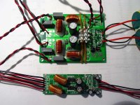
Finally, here's a photo of the Ref-T with output caps next to my "beater" AMP3 for comparison.
All I can say is that it works and sounds fabulous. There's a bit more detail and the soundstage sound a tad wider than before. I can't tell if it has more clean power because I don't want to play it too loud right now.
The power supply setup I'm using is most definitely overkill but that was all part of the experiment. Despite what Tripath said about using separate supplies, the Ref-T v1.0 board seems to work quite well but more testing is needed to see how it fares under differing conditions.
I have a rather large Digi-Key order coming in later this week and hope to have three boards fully built within two weeks so I can send a couple out to be tested/auditioned. I won't say who they'll be sent to so you'll just have to wait and see
Finally, here's a photo of the Ref-T with output caps next to my "beater" AMP3 for comparison.
Attachments
All of the regulation will be onboard as soon as I receive my Digi-Key shipmentpanomaniac said:Weren't you going to put regulation onboard? Or is it there and I don't see it?
Thanks! Yes, the audiophile elastomeric band was the heatsink attachment method of choice since I ran of thin double sided tapeserengetiplains said:Looks great, Brian! Good to hear it sounds promising (as it should). Looks like a winner.
I second the praise for the heat sink attachment. Special audiophile elastomeric properties, I assume?
 The chip doesn't even need a heatshink at my listening levels but it sure won't hurt anything.
I've been probing the amp with my oscilloscope and found some interesting things. The waveforms look nice and clean and almost look overdamped. That may be because I'm using my actual speakers as the load instead of an 8ohm resistor. There is a 200mV (100mV from each output that are 180 degrees out of phase) 1MHz (exactly) residual signal that rides the output waveform regardless of the signal being amplified or the level of amplification. For this measurement I have two probes hooked up with the grounds at power ground and the probes at the output of one channel and the scope set to differential mode.
Michael or anyone else - have you seen this when probing around your amps?
I'll try to take some pics of the scope so you all can see what's going on.
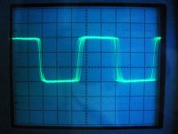
Here's the switching waveform while the amp is idling. 5V/div vertical, 0.2us/div horizontal.
Michael or anyone else - have you seen this when probing around your amps?
I'll try to take some pics of the scope so you all can see what's going on.
Here's the switching waveform while the amp is idling. 5V/div vertical, 0.2us/div horizontal.
Attachments
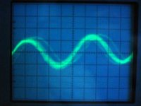
That residual just looks like the switching sqaure wave after filtration to me. Isn't it?
Your full blast square wave above looks mighty clean, no ringing. Never seen that before. But I always scoped on resistors, not drivers. Will try the with drivers and report back.
You have both the L and C in the filters now, right?
Your full blast square wave above looks mighty clean, no ringing. Never seen that before. But I always scoped on resistors, not drivers. Will try the with drivers and report back.
You have both the L and C in the filters now, right?
Hmm, I posted the horizontal scale wrong for that first photo. I thought I measured it at 0.5us/div. But yes, I thought it was just the switching frequency after the filter but was confused about the different frequency. I took my measurements at the output diodes before the inductors.

Ah geez! I had mislabeled the horizontal scale in the first photo because when I took the measurement it was at 0.5us per division. But I looked in another photo I took and saw that the little red 1X-10X knob was tweaked off center... yep, that'll do it. Gotta love these old analog scopes! In conclusion, you are correct and I will get that coffee soon!
Yes, the amp has the 41hz toroids (I measured them to be 13uH at 100kHz), 0.22uF film caps to ground, the Tripath recommended zobel/snubber, and 0.01uF differential cap right where the output wires leave the board.
and I will get that coffee soon!Yes, the amp has the 41hz toroids (I measured them to be 13uH at 100kHz), 0.22uF film caps to ground, the Tripath recommended zobel/snubber, and 0.01uF differential cap right where the output wires leave the board.
Great Work
Brian,
I am in Northern Virginia near the Nation's Capital. I am really interested in your work to date. I would love to hear your finished product. I would, also, be interested in a kit that already has the SMD devices in place.
There are a few mass assembly PCB firms in this area. Message me offline and I can forward the info to you, if you so desire.
Dave, I look forward to checking out whatever info you have to offer. Thanks.
I also just received the shipment with all the parts needed to fully build up a few boards. Sadly, I won't have time tonight and I'll be away all weekend so they won't get built for at least a few days.
I also just received the shipment with all the parts needed to fully build up a few boards. Sadly, I won't have time tonight and I'll be away all weekend so they won't get built for at least a few days.
Enjoy!
I well be putting the info together for you over the next couple of days . Hopefully, I will have it done by the time you get back. I trust that your weekend is fun filled and you have an opportunity to enjoy this marveloius weather we are having on the East Coast.
Enjoy!
I well be putting the info together for you over the next couple of days . Hopefully, I will have it done by the time you get back. I trust that your weekend is fun filled and you have an opportunity to enjoy this marveloius weather we are having on the East Coast.
Enjoy!
Here's one 90% complete board up and running. I got the 555 timers in the wrong package so I didn't solder that or any of its supporting components. I did put the rest of the stuff on the board though. 4 separate regulators, protection diodes, input and output caps, and the DC offset adjustment circuit. The output offset was easily adjusted to about 0.1mV on each channel with the pots at the inputs and neither the fault or overload LEDs have come on yet, so she's good to go! I've had the Ref-T playing every time I'm in the room so it's getting plenty of playing time. With the 3 Vdd regulators set to 14V they all run pretty warm without any extra heatsinking (as does the TA2021B) but you can easily hold your finger on each of them indefinitely so they're operating all right.
The main problem with using 4 discrete regulators is price and the extra components involved. For that reason I'll be focusing on a 2 regulator design where 1 regulator handles the 14V sections and another regulator handles the 5V sections. That will be a bit cheaper and allow the use of a better regulator. I used LM338s and an LM340 for the 14V and 5V regulators on the board in the photo.
The sound is also about the same as when I was using the off board regulators. I didn't expect much improvement and I really couldn't hear any difference either way. The imaging is superb, the bass is improved without taking away from the top end, and it still has the same clean detailed class d sound without being fatiguing. I can try replacing the mylar caps in the output filter with polypropylene ones I have but I don't think that will make any noticeable difference either. I'm very happy with the sound as is. Now I just have to get another one built so someone else can audition one! I will likely try this amp with some larger Klipsch speakers as well. If this amp makes my small Definitive monitors sound big it should make the larger Klipsch's really kick out the jams (to borrow a line from Rage Against the Machine).
Attachments
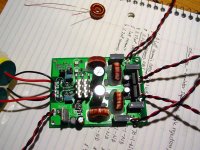
Well, after what I did to the amp the other day you won't be hearing it for a little while. Since I have a separate input for each supply I was fiddling around with the wiring a little. I've got a wallwart for the 14V on-chip mosfet driving section and a separate secondary of a larger dual secondary transformer was used for each channel's regulator. Anyway, I was playing music and switched off my large transformer. It played for about a minute since each secondary has 22000uF after it's rectifier, then I saw both the overload and fault LEDs light up. At first I thought, hey they work!... then I felt that one of the regulators and the chip was rather hot, so I pulled the power and checked a few things. Somehow, the mosfets on one output of one channel were fried because I see 6.7V on all outputs but one when the amp is powered and awake. The bad output is showing 2.17V. That's the only evidence of damage that I could find. Some other components inside the chip could have been damaged as well. Looks like I'll have to replace the chip if I want it to play music again... Ah well, I was wondering how long it would take me to nuke a chip
Moral of the story (I think): it seems that separate regulators can be used, BUT they must all power up at the same time (or get their input from the same power source) or some part of the chip will probably get damaged.
Moral of the story (I think): it seems that separate regulators can be used, BUT they must all power up at the same time (or get their input from the same power source) or some part of the chip will probably get damaged.
I'm waiting on some TA2021B chips so I can resurrect the dead Ref-T but have already ordered 6 boards for the next version of the Ref-T. These will be the ones that I'll build up and have some people audition.
This latest version (v1.2) is different from the first version (v1.0) in a few different ways (v1.1 was an iteration of v1.0 that was scrapped when I started v1.2). The key differences are in the power supply components and layout. There are only two on board regulators now. One for the 14V sections and one for the 5V sections. There is room on board for 4 supply caps with space for ferrite beads or inductors between the caps. This should provide good filtering for the each output channel and will help to keep them more separate from one another. The 14V driving section also has a ferrite bead and an electrolytic cap for filtering. An electrolytic cap was also added to the 5V supply section. The overload status LED circuit was removed from the board and the fault and power LEDs are now driven from the TA2021B internal 5V regulator instead of the 14V driving supply. Room for small film input coupling caps was made on the input side. The board layout changed dramatically on the output side but remained largely the same on the input side.
I'll let ya'll know how it sounds when I get one built in a couple of weeks.
Oh, the attached image should be the actual size of the amp.
Attachments
Hey Brian,
Sorry to hear that you fried one, but that's what research is all about, right?
Maybe you found that weak connection between channels.
Your idea of 2 regulators is still good, as I suspect a lot of the crosstalk on these amps is coming thru the power supply rail.
I've been busy this week, bit should have some interesting tests to show for it.
A sneak preview:
Batteries may not be as quiet as you think.
Linear PSU is better than SMPS, but SMPS is very good, done right.
T-Amp pulse response is good and be made better. (Almost perfect)
Switching harmonics can be improved.
Noise comes from places you wouldn't suspect.
Most T-amps have a noise floor lower than your CD player.
Keep up the good work, I'm looking forward to trying one of your Ref-Ts.
- Status
- This old topic is closed. If you want to reopen this topic, contact a moderator using the "Report Post" button.
- Home
- Amplifiers
- Class D
- My Ref-T amp