Details in my circuit are weak design. I need to enhance the driver, in order to ensure it's swing exactly down to -50V and guarantee no positive values at all.
But I started simulation and the delay beween the crossing of audio and triangle to output is in the range of below 100 nsec delay. That seems promising.
The 3-triode design will be a 3-double-triode design. Fun fact: 3 times 7.5V/0.3A heating is easy to get with my 12V/24V transformers.
The Mullard datasheet for PCC89 indicates 15mA as nominal anode current and 90V nominal and 130V max. Others specify 20mA max.
The 3-triode design will be with 1 single common cathode current source.
Use of the differential stage (2 of three triodes) is the best option for symmetric, fast and opposite output to the GU50 gates.
The anode resistors and anode current in fact dominates the rising time at the gate of the GU50.
I will update the schematics, when I am satisfied with secure swing at GU50 gate 1.
The magnetic discharge will be changed to double the winding, center tap and use 2 pretty EY500 for discharge.
Greetings,
Joachim
Last edited:
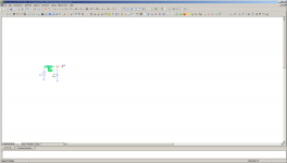
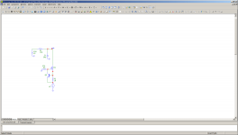
The simplified circuit, but with driver stages fully drawn.
The tuning of the 3-triode differential amp (with double systems) is done with the resistors. Maybe, I add a supervising circuit, which ensures the g1 swing between -50V and -1V at those 4 GU50.
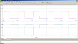
The 3-triode circuit is driven with 2 rectangular signals in harmonic frequencies.
One represents the 'PWM' with 50/50% at idle, silent audio, the other is the magnetic discharge control. It will have a 33/66% constant ratio, in order to fully discharge the EC102 ferroxcube magnetic energy. Keeping this ratio is a security measure.
The GU50 will switch between almost 0 and 300mA each.
Here:

Greetings from Hamburg,
Stay tubed in the new year!
Joachim
The tuning of the 3-triode differential amp (with double systems) is done with the resistors. Maybe, I add a supervising circuit, which ensures the g1 swing between -50V and -1V at those 4 GU50.
The 3-triode circuit is driven with 2 rectangular signals in harmonic frequencies.
One represents the 'PWM' with 50/50% at idle, silent audio, the other is the magnetic discharge control. It will have a 33/66% constant ratio, in order to fully discharge the EC102 ferroxcube magnetic energy. Keeping this ratio is a security measure.
The GU50 will switch between almost 0 and 300mA each.
Here:
Greetings from Hamburg,
Stay tubed in the new year!
Joachim
Below or near 2.5 kOhmWhat practical value of Zra1 Zra2 resistors you planning to use ?
30mA == 15 mA each. Anode voltage swing to ~ 5mA is 50 V; in idle, silence this is 50% of 1.5 W max anode dissipation ?Thats about 16W of heat on each of them ( 250v - 50v) ,and also rise time not guaranteed . Better i think would be use same type tube as dynamic load or as CCS in place of these resistors .
I know, resistors are limited. But look at the current per voltage of GU50, that is not too bad.
You said swing for gu50 is 50volts .Supply voltage +250V, GU50 cathode is on ground potential. So one resistor end is at +250V always ,another end is at about ground potential (when gu50 is off) and about +50V when GU50 is ON .So simple mathematics : ((250V - 50V)*(250V-50V))/2500 Ohms . So resistor dissipates 200 to 250V on its 2,5k , P=U*U /R . 200*200/2500 = 16W .And also current is 80ma for each resistor when GU is on ,and even more ,if OFF .
Hi ximikas,You said swing for gu50 is 50volts .Supply voltage +250V, GU50 cathode is on ground potential. So one resistor end is at +250V always ,another end is at about ground potential (when gu50 is off) and about +50V when GU50 is ON .So simple mathematics : ((250V - 50V)*(250V-50V))/2500 Ohms . So resistor dissipates 200 to 250V on its 2,5k , P=U*U /R . 200*200/2500 = 16W .And also current is 80ma for each resistor when GU is on ,and even more ,if OFF .
You misunderstand the GU50 - it is on at g1 at near 0, full anode current. It is off at -50V at the gate.
The resistor might be lowered, if I stabilize an anode voltage for the PCC89 at lower values, but I currently do not see advantage, to do so.
I just need a ~ 50V swing, between -1 and -50 Volts.
If I take the statistic -25V Volts and keep 30mA max for all 3 triode pairs, the resistor is at ~ 285V with statistic 15mA dissipating 4.275W average. Audio dominates.
It's DC resistance will be 10KOhms, not 2.5k.
Still good for MHz frequency maximum, but slowest part.
The amount of energy dissipated by the anodes resistors does not matter at all. Compared to anode heat energy of the GU50, this is not significant.
I am not satisfied with the danger of missing my required swing, depending on the driving opamp's accuracy and would wish a higher slew rate at g1 of GU50.
Replacing the triode anode resistors of the triode pairs has no convincing circuit, yet.
Another triode pair wouldn't change much. 30mA...
Remember: I have varying PWM for an extended number of periods.
The slope will be defined by the almost constant 30mA and 2x13pF gate capacity.
Maybe I am better off with lowering triangle frequency, still keeping it apart from an audible intermediate from magnetic discharge frequency.
Greetings,
Joachim
Last edited:
Hi, congratulations entering new year first !
So , if GU50 needs negative voltage at gate to be off ,then its not effective to connect those resistors to +250V , upper ends better will be at lets say +5v or something closer to ground .Then for driver it would be easier to drive them ,and you may even try to reduce them .
So , if GU50 needs negative voltage at gate to be off ,then its not effective to connect those resistors to +250V , upper ends better will be at lets say +5v or something closer to ground .Then for driver it would be easier to drive them ,and you may even try to reduce them .
Hi ximikas,Hi, congratulations entering new year first !
So , if GU50 needs negative voltage at gate to be off ,then its not effective to connect those resistors to +250V , upper ends better will be at lets say +5v or something closer to ground .Then for driver it would be easier to drive them ,and you may even try to reduce them .
Thanks a lot, whish the same to you!
Your proposal will work fine with fast FET semiconductors. Tubes need higher voltage to get fast, semiconductors get slower, because of their required channel length and insulating, driving gates. Which will have high capacities for high drive capabilities.
I decided to use tubes and want to see, what they are able to do.
Phese PCC89 are last generation UHF cascode amps / mixers / oscillators. 200 MHz is their intended use. While I need 250V for g2 of the GU50, this voltage is a bit high for a cold PCC89. The PCC89 will withstand that.
Today morning, my headage doesn't allow the precise calculations, but I will do it, by today:
Just need to know, how fast the g1 of GU50s will travel from -1 to -55V with it's 26pF capacities with 30mA constant current.
Greetings,
Joachim
2,5k resistor and 26pf makes a nice filter for even slow frequencies ... You will get a closer to triangle to sawtooth with resistive driver load .And this is not include sockets capacity ,output tubes capacity ,wires ,pcb and so on. Screenshot from microcap sim attached . Red is pulse source ,set to 100ns rise and fall times ,50V amplitude ,and blue is what you get after resistor value 2,5k . You said 10k ... That's worse .To be more precise , need to be simulated from higher voltage source, it may improve a bit .
Attachments
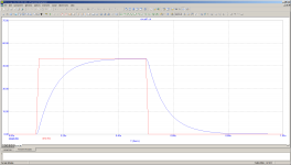
Your circuit is not comparable: the voltage source is not 50V and the slope will keep the high rate from start. Constant current!2,5k resistor and 26pf makes a nice filter for even slow frequencies ... You will get a closer to triangle to sawtooth with resistive driver load .And this is not include sockets capacity ,output tubes capacity ,wires ,pcb and so on. Screenshot from microcap sim attached . Red is pulse source ,set to 100ns rise and fall times ,50V amplitude ,and blue is what you get after resistor value 2,5k . You said 10k ... That's worse .To be more precise , need to be simulated from higher voltage source, it may improve a bit .
We need a calculation with Coulomb, current, capacity. The current is only defined by the resistor, in upper slope. The triodes define the currents.
Parasitics are more, but the gate capacity dominates.
Triodes define current only in one direction , when voltage at GU50 input is going to be negative . When voltage is coming close to ground ,turning ON GU50 ,resistor resistance dominates . Your driver is currently assymetric output . Negative swing is dominated by triodes ,thats right ,but positive - by resistor . Rise time will be different than fall time i think .Yes ,i agree, my circuit is not accurate ,but its showing a resistor effect with input capacity of tubes .Maybe i should try another simulation with current source to negative ,but i don't think it will improve rise time , only fall time .
Try to use just the 10K with 250V and start from -55V , stop at 0. 😎Triodes define current only in one direction , when voltage at GU50 input is going to be negative . When voltage is coming close to ground ,turning ON GU50 ,resistor resistance dominates . Your driver is currently assymetric output . Negative swing is dominated by triodes ,thats right ,but positive - by resistor . Rise time will be different than fall time i think .Yes ,i agree, my circuit is not accurate ,but its showing a resistor effect with input capacity of tubes .Maybe i should try another simulation with current source to negative ,but i don't think it will improve rise time , only fall time .
Start will be at little bit more then 30mA, Stop at 25mA.
Last edited:
Looks good at first glance. But there are semiconductors, uuuh. And I am in doubt about their dynamic parameters...
They could start overshoots, ringing... (All my work life worked with them, I promise).
What is the slew rate?
Let us try simple. Just with: let the triode react large signal, from 30mA to just 1 mA, to keep it running. In order to raise anode current to 30mA ASAP. The cap of 26pF is then discharged trough resistor over a swing of 54V with 30mA at the beginning, 25 mA near finish. The last mA is drawn somewhere, no matter, how. We just want stay at -1V and at -55V, respectively.
Average current is 27.5mA. Charge within g1 at start will be 1.04nC. At the end it will be 0.026nC. Simplify to 1nC. Slope time will be 36,36 nsec.
If we count up other parasitics, this might be 40nsec. Just for this gate drive. Not too bad!
It is clear, this is not the full story. Both tubes have dynamics. The resistor will have inductance.
If I use a triangle frequency of 100kHz, but still, I expect the transformer will dominate all the transitions.
The PCC89 might have a large signal frequency output of 100MHz, a cycle of 10nsec and the GU50 is even faster. At 100kHz triangle and silent audio, the cycle is 10usec, high and low state times are quite large 5usec, compared to 40nsec transition (not taking the transformer into calculation).
If I just clamp the g1 voltages with tube diodes, that could simplify the design of the triode driving circuit.
Greetings,
Joachim
t
What about RF noise ,which can be catched by your opamp and audio input circuits ? Hundreds voltage swing with fast rise and fall times can easy disturb operation of other parts ,also your neighbour's tv ") Very very good shielding needed for inputs ,low input resistance ,and proper ground wiring . Also for proper high frequency audio reproduction ,100khz is a bit too low i think ,but for frequencies like sub or middle its ok .One thing is sinewave 20khz ,and another story is real audio signal ,with high slew rates ,in electronic music in example . Your first idea about 200 or 240khz was much better . Also another thing , your discharge circuit ,do you think its 40 or 80khz operation will not appear at output transformer and will not affect feedback ?
Very very good shielding needed for inputs ,low input resistance ,and proper ground wiring . Also for proper high frequency audio reproduction ,100khz is a bit too low i think ,but for frequencies like sub or middle its ok .One thing is sinewave 20khz ,and another story is real audio signal ,with high slew rates ,in electronic music in example . Your first idea about 200 or 240khz was much better . Also another thing , your discharge circuit ,do you think its 40 or 80khz operation will not appear at output transformer and will not affect feedback ?
First practical tests should be without feedback ,just to check how transformer ,GU50, driver are functioning .
Very very good shielding needed for inputs ,low input resistance ,and proper ground wiring . Also for proper high frequency audio reproduction ,100khz is a bit too low i think ,but for frequencies like sub or middle its ok .One thing is sinewave 20khz ,and another story is real audio signal ,with high slew rates ,in electronic music in example . Your first idea about 200 or 240khz was much better . Also another thing , your discharge circuit ,do you think its 40 or 80khz operation will not appear at output transformer and will not affect feedback ?First practical tests should be without feedback ,just to check how transformer ,GU50, driver are functioning .
You are right, shielding electrostatic and magnetic fields is important. It is all RF and having power. But that is known, how to handle that. I have lots of material for that.What about RF noise ,which can be catched by your opamp and audio input circuits ? Hundreds voltage swing with fast rise and fall times can easy disturb operation of other parts ,also your neighbour's tv
First practical tests should be without feedback ,just to check how transformer ,GU50, driver are functioning .
100kHz is just one number to make visible the relations. I will tune it and expect the biggest challenge in the transformer design. My experience with bigger SMPS and servo motor drives might help. It triggered this entirely.
High slew rates in audio might be there, I cut off anything, our ear will not recognize: Limit is 20kHz. I might need to protect my speakers, too.
I thought a lot about the discharge period. After some time, I recognized it's potential distortion to output and decided to treat it as one additional signal at the ouput winding. It's amplitude and polarity is dependent on audio amplitude and higher near low frequencies and it will directly relate to audio because of energy.
So, it is not just random noise!
That quickly made clear, I need a frequency, which is not only far from audio, it must be in a fixed relation to the base triangle.
When looking at normal transformers, they hardly transform above 20kHz at all. Large signal, high frequency transfer is done through the windings, not the core. So I expect to get a good result with a sharp low pass to anything below 20kHz.
Feedback will work somewhere below 10 kHz, where you can recognize it with ears.
Also, a matter of tuning.
Yes ,filter above 20khz is done always in class D amps ,to prevent uncorrectable distortions and other misoperation .But this filtering also affects audio quality. Yes ,human ear hardly hears high frequencies directly ,but depending on audio material ,there may be clearness loss after filter ,if used in AB amplifiers ,have proven that myself many times .Even if filter was set to 130khz cut ,but there was small audible difference when decreasing its capacitor and adding another one while playing. Also simulations showed me earlier about input filter affecting signal even from 1khz ,at lower values like +-0.1db ,but still . But this is D class ,different requirements ,also need to filter out received noise from itself . Another thing you mentioned was ringing , i think transformer will dominate there.
Hi ximikas,Yes ,filter above 20khz is done always in class D amps ,to prevent uncorrectable distortions and other misoperation .But this filtering also affects audio quality. Yes ,human ear hardly hears high frequencies directly ,but depending on audio material ,there may be clearness loss after filter ,if used in AB amplifiers ,have proven that myself many times .Even if filter was set to 130khz cut ,but there was small audible difference when decreasing its capacitor and adding another one while playing. Also simulations showed me earlier about input filter affecting signal even from 1khz ,at lower values like +-0.1db ,but still . But this is D class ,different requirements ,also need to filter out received noise from itself . Another thing you mentioned was ringing , i think transformer will dominate there.
let me understand: class AB with transformers include iron cores, which have a hysteresis - The type of distortion you can produce with hysteresis is quite complex and will never be compensateble at all. So the effects to these cores, when changing driving currents are very, very unpredictable.
Do we talk about this ?
Grettings,
Joachim
- Home
- Amplifiers
- Class D
- tubes in Class D?