FYI, the reason the output filter caps were chosen at only 470 uF was quite deliberate. One common failure mode of linear audio amps is shorting of the power transistors due to overloads. This in turn is often caused by the amount of energy available in the filter caps of a conventional power supply, which must be large to reduce 60Hz ripple to acceptable levels. Fuses are often too slow to limit damaging energy from reaching the FETs, and fast protection circuits cause audible problems under some normal signal circumstances.
With a switching supply, the opportiunity exisats to provide sufficuient energy for any reasonable load and signal, yet limit the available energy to a level that can avoid transsitor damage. That was our intent. The ripple doesn't make it to the audio output by common mode rejection in the amp and in any case those frequencies are well out of the audio band.
Gertjan is correct - the LED load resistor should be a higher value, like 1 or 1.5K.
Reinhard Metz
rmetz said:FYI, the reason the output filter caps were chosen at only 470 uF was quite deliberate. One common failure mode of linear audio amps is shorting of the power transistors due to overloads. This in turn is often caused by the amount of energy available in the filter caps of a conventional power supply, which must be large to reduce 60Hz ripple to acceptable levels. Fuses are often too slow to limit damaging energy from reaching the FETs, and fast protection circuits cause audible problems under some normal signal circumstances.
With a switching supply, the opportiunity exisats to provide sufficuient energy for any reasonable load and signal, yet limit the available energy to a level that can avoid transsitor damage. That was our intent. The ripple doesn't make it to the audio output by common mode rejection in the amp and in any case those frequencies are well out of the audio band.
Gertjan is correct - the LED load resistor should be a higher value, like 1 or 1.5K.
Reinhard Metz
Hello Reinhard,
Thanks for the comments, maybe you could/should notify your previous customers to replace R40 with a 1k or a 1.5k resistor.
I agree with your comments on why you use 2x470uF per rail, in combination with a shutdown that is for example triggered by a DC protection circuit, the amp/speakers can be protected without using any relays in the signal path or in the supply path. Good amps have good PSRR so the ripple should be no issue.
My main use for the shutdown mode would be to connect it later to a DC detection circuit. Say the amps outputs DC but draw not enough current to trigger the overcurrent protection, say 10A or so. It will take probably at least something in the order of 100-200ms, maybe even longer, to detect DC since you don't want to trigger the DC protection for a 20Hz (or lower) home theater bass signal, so you will have a big current running for at least a few 100ms before the DC protection detects it. If the supply is then shutdown, the 2x470uF caps will be drained empty quickly. However, even a 10.000uF cap that is loaded with say 10A, will be drained in less than 100ms. Since it already takes several hundred ms to detect DC, I think that additional time to drain the 10.000uF caps maybe acceptable.
Besides that, my amp modules (UcD) have overcurrent protection themselves, so for the overcurrent protection, I don't need the supply. In my particular case, I want to use the supply to behave like a real high-end supply by adding some extra caps at the output, this allows me to increase the feedback which further improves the stabilityof the output voltage. As a result, with only one additional 10.000uF cap per rail, you have the ripple of something like 100.000uF with a conventional supply and only 10% of the stored charge/energy.
Maybe I will add a manual reset switch to reset the shutdown latch circuit if I happen to trip the overcurrent protection too often, I don't expect that to ba an issue however. The supply has proven to be very robust as it was tortured quite a bit by those repetitive shutdown and overcurrent conditions. You could here some sound from the supply during the overcurrent situation, however, no smoke, heat, nothing, the lights went down a bit as well
") .
.Best regards
Gertjan
ghemink said:
And here is the AC residue on the power rail (only positive rail shown).
About 400mV peak/peak LF residue (100Hz + harmonics) and only about 40mV peak/peak for the HF residues. And this is at a load of 5.4A on both rails with both rails at 64V, so delivering 690W power.
I think I have a hell of a power supply here that is immune to changes in the load current and has very low LF and HF ripple.
Thanks to Reinhard for this supply that I could further optimize in a relatively simple way. Hopefully this weekend, I can hook up some of my UcDs to see how it works with the amps.
Best regards
Gertjan
I have done some more experiments/mods.
As mentioned in an earlier mail, I changed R40 from 316Ohm to 1k to make the shutdown circuit work correctly. I removed Q5 to disable the recovery after a shutdown. The supply needs tobe recovered after a shutdown by powering down and up again. This is the safest approach.
I added an RC delay to the Vref that is going to pin 5 of IC2 using a 100k resistor and a 10uF cap, actually you can R24 and C9 for that since these are not needed when one disables the recovery. This results in a nice clean startup of the supply without any overshoots.
I went to Akihabara yesterday and found some 100V 1000uF caps that can be used to replace the standard 470uF 100V caps at the output. This would increase the onboard filter capacity to 2000uF per rail (from 940uF). This gives slightly less mains related harmonics and also slightly less HF rests.
I also found out that a large part of the HF noise that I measured before was due to the scope probes picking up switching noise. I remeasured the noise by using a shielded speaker cable with the + and - of the cable directly connected to the output caps and the shield directly to GND of the output caps. I guess this is the cleanest way. Then this cable went to the dummy load and the scope prbes were connected at the dumy load. This gave a much cleaner signal as you will see later.
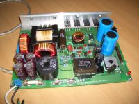
Attached is a picture of the supply, it is quite big about 19x24cm and about 6.5cm high.
More pictures in following posts
Gertjan
Attachments
ghemink said:
I have done some more experiments/mods.
As mentioned in an earlier mail, I changed R40 from 316Ohm to 1k to make the shutdown circuit work correctly. I removed Q5 to disable the recovery after a shutdown. The supply needs tobe recovered after a shutdown by powering down and up again. This is the safest approach.
I added an RC delay to the Vref that is going to pin 5 of IC2 using a 100k resistor and a 10uF cap, actually you can R24 and C9 for that since these are not needed when one disables the recovery. This results in a nice clean startup of the supply without any overshoots.
I went to Akihabara yesterday and found some 100V 1000uF caps that can be used to replace the standard 470uF 100V caps at the output. This would increase the onboard filter capacity to 2000uF per rail (from 940uF). This gives slightly less mains related harmonics and also slightly less HF rests.
I also found out that a large part of the HF noise that I measured before was due to the scope probes picking up switching noise. I remeasured the noise by using a shielded speaker cable with the + and - of the cable directly connected to the output caps and the shield directly to GND of the output caps. I guess this is the cleanest way. Then this cable went to the dummy load and the scope prbes were connected at the dumy load. This gave a much cleaner signal as you will see later.
Attached is a picture of the supply, it is quite big about 19x24cm and about 6.5cm high.
More pictures in following posts
Gertjan
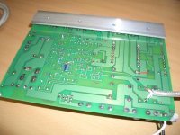
Bottom of PCB
Attachments
Attachments
ghemink said:
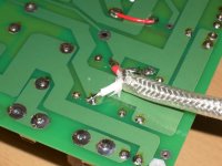
Shielded speaker wire connected at output caps
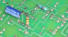
And the Vref RC filter with the cap between pin 4 and 5 of IC2, the copper trace under the resistor has been cut (not visible).
The other resistor is R25 of the feedback network, I increased it from 7k to 15k for the version with the 2x1000uF per rail, it is still mounted at the back of the PCB for easier access.
At the right, you can also see a blank wire. That wire is used to close the feedback loop. I had openend the feedback loop (by cutting a PCB trace) at that point to measure the open loop behavior in the past.
Attachments
ghemink said:
And the Vref RC filter with the cap between pin 4 and 5 of IC2, the copper trace under the resistor has been cut (not visible).
The other resistor is R25 of the feedback network, I increased it from 7k to 15k for the version with the 2x1000uF per rail, it is still mounted at the back of the PCB for easier access.
At the right, you can also see a blank wire. That wire is used to close the feedback loop. I had openend the feedback loop (by cutting a PCB trace) at that point to measure the open loop behavior in the past.
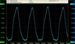
This is the AC residue with a 23.4 Ohm load, almost 5.5A current. with the 2x470uF per rail and the 7k feedback resistor (original)
Much cleaner than in the past, HF components are very small and 100Hz peak to peak about 1.8V or so
Attachments
ghemink said:
This is the AC residue with a 23.4 Ohm load, almost 5.5A current. with the 2x470uF per rail and the 7k feedback resistor (original)
Much cleaner than in the past, HF components are very small and 100Hz peak to peak about 1.8V or so
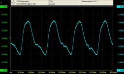
This is for the version with 2x1000uF per rail and feedback resistor increased from 7k to 15k, this gives about a factor 2 reduction in 100Hz mains related ripply to about 1V peak/peak
Attachments
ghemink said:
This is for the version with 2x1000uF per rail and feedback resistor increased from 7k to 15k, this gives about a factor 2 reduction in 100Hz mains related ripply to about 1V peak/peak
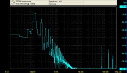
This is the spectrum of the previous figure
HF components at 75kHz and 150kHz are below -50dBV, this is about 3mV peak/peak for the 75kHz component, remember, this is at 5.5A load with the supply delivering about 700W power.
So very good HF behavior.
Best regards
Gertjan
Attachments
ghemink: Big respect for Your research and a lot of useful info!
But one thing that I'm not sure that 28:14+14 turns of power tr-r is enough for larger (about 80V) output voltages (larger duty cycle). Maybe it 56:28+28 ? Could You wind 5-10 turns of wire-wrap on the power tr-r and measure pulses amplitude? I think this info will helpful for DIY builders.
But one thing that I'm not sure that 28:14+14 turns of power tr-r is enough for larger (about 80V) output voltages (larger duty cycle). Maybe it 56:28+28 ? Could You wind 5-10 turns of wire-wrap on the power tr-r and measure pulses amplitude? I think this info will helpful for DIY builders.
Dem said:ghemink: Big respect for Your research and a lot of useful info!
But one thing that I'm not sure that 28:14+14 turns of power tr-r is enough for larger (about 80V) output voltages (larger duty cycle). Maybe it 56:28+28 ? Could You wind 5-10 turns of wire-wrap on the power tr-r and measure pulses amplitude? I think this info will helpful for DIY builders.
Thanks for your interest. I"m a bit busy at work these days so my progress has slowed down a bit.
Whether it is 56:28+28 or 28:14+14 should not make much difference, should it? I have measured the signal after the transformer, before the LC filter. The amplitude of the pulses indicates that it is a 2n:n+n transformer. The pulses are 150Khz pulses and duty cycle is close to 50% giving about 64V in my case.
I may try later to add a winding to be sure.
Best regards
Gertjan
Heat sink requirement
Hi Gertjan,
Excellent work. One thing I was wondering about. Have you hooked up the power supply to any kind of heat sink while you've been doing your various tests, or has it stayed cool enough without any heatsink? Do you think that just bolting it to the side of a case would provide enough heat dissipation?
Re: Heat sink requirement
Hi Greg,
During my tests, in many cases, I had it floating in air, just the simple L profile. Just recently, I mounted the supply using another slightly bigger aluminum L profile on a piece of aluminum *2mm thick and 25 x25cm. During my tests, it stayed cool enough even without any heatsinking (so only the L profile) even when loading it with 5A load. However, these test were for short periods since I dont want to overheat anything. In fact, the dummy loads that had to dissipate those 600-700W were getting much hotter than the supply without any heatsinking.
Hopefully in the not so far future, I plan to hook it up to a few UcD modules and try it out for a subwoofer application. I plan not to use a heatsink, just mounting it with another L-profile to the bottom of an aluminum case. I will check whether the temperature stays sufficiently low.
The configuration I now plan to use for first tests with UcD modules uses the 1000uF caps on the supply board (so total 2000uf per rail) and adding a 10.000uF ELNA Cerafine 63V per rail. I changed the resistor in the feedback loop from 7k to 33k and supply is stable at high current (tested upto about 700W).
I also lowered the output voltage from about 63-64V to about 58-59V since I do not want to risk the ELNA caps (changing two resistors).
Best regards
Gertjan
GregD said:Hi Gertjan,
Excellent work. One thing I was wondering about. Have you hooked up the power supply to any kind of heat sink while you've been doing your various tests, or has it stayed cool enough without any heatsink? Do you think that just bolting it to the side of a case would provide enough heat dissipation?
Hi Greg,
During my tests, in many cases, I had it floating in air, just the simple L profile. Just recently, I mounted the supply using another slightly bigger aluminum L profile on a piece of aluminum *2mm thick and 25 x25cm. During my tests, it stayed cool enough even without any heatsinking (so only the L profile) even when loading it with 5A load. However, these test were for short periods since I dont want to overheat anything. In fact, the dummy loads that had to dissipate those 600-700W were getting much hotter than the supply without any heatsinking.
Hopefully in the not so far future, I plan to hook it up to a few UcD modules and try it out for a subwoofer application. I plan not to use a heatsink, just mounting it with another L-profile to the bottom of an aluminum case. I will check whether the temperature stays sufficiently low.
The configuration I now plan to use for first tests with UcD modules uses the 1000uF caps on the supply board (so total 2000uf per rail) and adding a 10.000uF ELNA Cerafine 63V per rail. I changed the resistor in the feedback loop from 7k to 33k and supply is stable at high current (tested upto about 700W).
I also lowered the output voltage from about 63-64V to about 58-59V since I do not want to risk the ELNA caps (changing two resistors).
Best regards
Gertjan
Re: Heat sink requirement
More updates in my following posts.
I decided to make this supply high-end. I had a whole bunch if 63V 8200uF caps at home that I originally intended to use for a conventional supply. I used 8 of them, 4 for each rail and I connected them via a R-C-R like setup in parallel. For the R, I used a value of 0.1 Ohm. I topped it off at the end with anothe C per rail. Those were Elna Cerafines 10000uF 63V. These caps I also had, so I'd better use them since they were pretty expensive.
So together with the 2000uF per rail on the SMPS board, this brought the total capacitance at the output to 44800uF. This brings the resonace frequency of the out put LC filter to 40Hz and with a very low Q.
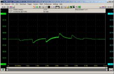
I changed the R and C in the feedback network to 33k and 4.9uF (the original 0.22uF and a 0.47uF non-polar BG in parallel). (R=R25 and C=C25 in the schematics). This results in the integrator pole to have a corner frequency at 1Hz. This means that I have a lot of phase margin and slow regulation as you can see in the attached figure.
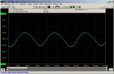
The attached figure shows the output voltage during switching of the loads. Initial current is about 0.35A, then switched to about 0.7A, then to about 2.9A and then to about 5.1A, and then back again in the same order. You can see that the integrator in the feedback loop tries to bring back the DC output level after each switching event, it does that very slow due to the low corner frequency. Current flows between both rails, so supplying about 600W max. Voltage drops during switching about 200-250mV per ampere load. Not bad I would say, can be reduced if you make the integrator faster, and drop will be less at audio frequencies anyway.
GregD said:Hi Gertjan,
Excellent work. One thing I was wondering about. Have you hooked up the power supply to any kind of heat sink while you've been doing your various tests, or has it stayed cool enough without any heatsink? Do you think that just bolting it to the side of a case would provide enough heat dissipation?
More updates in my following posts.
I decided to make this supply high-end. I had a whole bunch if 63V 8200uF caps at home that I originally intended to use for a conventional supply. I used 8 of them, 4 for each rail and I connected them via a R-C-R like setup in parallel. For the R, I used a value of 0.1 Ohm. I topped it off at the end with anothe C per rail. Those were Elna Cerafines 10000uF 63V. These caps I also had, so I'd better use them since they were pretty expensive.
So together with the 2000uF per rail on the SMPS board, this brought the total capacitance at the output to 44800uF. This brings the resonace frequency of the out put LC filter to 40Hz and with a very low Q.
I changed the R and C in the feedback network to 33k and 4.9uF (the original 0.22uF and a 0.47uF non-polar BG in parallel). (R=R25 and C=C25 in the schematics). This results in the integrator pole to have a corner frequency at 1Hz. This means that I have a lot of phase margin and slow regulation as you can see in the attached figure.
The attached figure shows the output voltage during switching of the loads. Initial current is about 0.35A, then switched to about 0.7A, then to about 2.9A and then to about 5.1A, and then back again in the same order. You can see that the integrator in the feedback loop tries to bring back the DC output level after each switching event, it does that very slow due to the low corner frequency. Current flows between both rails, so supplying about 600W max. Voltage drops during switching about 200-250mV per ampere load. Not bad I would say, can be reduced if you make the integrator faster, and drop will be less at audio frequencies anyway.
Attachments
Re: Re: Heat sink requirement
The AC ripple at 5.1A load is now much smaller than before, what do you expect with all those caps. It is about 100mV peak/peak and only has low frequency content. HF rests are very low.
ghemink said:
More updates in my following posts.
I decided to make this supply high-end. I had a whole bunch if 63V 8200uF caps at home that I originally intended to use for a conventional supply. I used 8 of them, 4 for each rail and I connected them via a R-C-R like setup in parallel. For the R, I used a value of 0.1 Ohm. I topped it off at the end with anothe C per rail. Those were Elna Cerafines 10000uF 63V. These caps I also had, so I'd better use them since they were pretty expensive.
So together with the 2000uF per rail on the SMPS board, this brought the total capacitance at the output to 44800uF. This brings the resonace frequency of the out put LC filter to 40Hz and with a very low Q.
I changed the R and C in the feedback network to 33k and 4.9uF (the original 0.22uF and a 0.47uF non-polar BG in parallel). (R=R25 and C=C25 in the schematics). This results in the integrator pole to have a corner frequency at 1Hz. This means that I have a lot of phase margin and slow regulation as you can see in the attached figure.
The attached figure shows the output voltage during switching of the loads. Initial current is about 0.35A, then switched to about 0.7A, then to about 2.9A and then to about 5.1A, and then back again in the same order. You can see that the integrator in the feedback loop tries to bring back the DC output level after each switching event, it does that very slow due to the low corner frequency. Current flows between both rails, so supplying about 600W max. Voltage drops during switching about 200-250mV per ampere load. Not bad I would say, can be reduced if you make the integrator faster, and drop will be less at audio frequencies anyway.
The AC ripple at 5.1A load is now much smaller than before, what do you expect with all those caps. It is about 100mV peak/peak and only has low frequency content. HF rests are very low.
Attachments
Re: Re: Re: Heat sink requirement
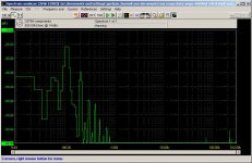
The spectrum analyzer view shows the 100Hz, 200Hz and a few higher harmonics. The HF components are below -85dBV, that is less than 50uV peak/peak for each HF component (75kHz and 225kHz). I used 14 bit resolution on the scope and 200mV range with AC coupling to measure this.
ghemink said:
The AC ripple at 5.1A load is now much smaller than before, what do you expect with all those caps. It is about 100mV peak/peak and only has low frequency content. HF rests are very low.
The spectrum analyzer view shows the 100Hz, 200Hz and a few higher harmonics. The HF components are below -85dBV, that is less than 50uV peak/peak for each HF component (75kHz and 225kHz). I used 14 bit resolution on the scope and 200mV range with AC coupling to measure this.
Attachments
Re: Re: Re: Re: Heat sink requirement
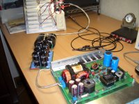
This was my test setup. In front the SMPS mounted on an aluminum plate of 25x25cm, behind that the output caps and in the background the dummy load. With the switches I can change the load resistance.
ghemink said:
The spectrum analyzer view shows the 100Hz, 200Hz and a few higher harmonics. The HF components are below -85dBV, that is less than 50uV peak/peak for each HF component (75kHz and 225kHz). I used 14 bit resolution on the scope and 200mV range with AC coupling to measure this.
This was my test setup. In front the SMPS mounted on an aluminum plate of 25x25cm, behind that the output caps and in the background the dummy load. With the switches I can change the load resistance.
Attachments
Re: Re: Re: Re: Re: Heat sink requirement
So I guess, this one is now high-end enough to power a couple of UcD400 amps. With all those caps, power supply pumping should not be an issue. Nevertheless, I still plan to bridge two UcD400 maps for the woofers so it should not be much of an issue anyway.
I may add a few more RCR paralleled caps and two ELNAs (I have them, why not use them) to make a seperate branch maybe for the tweeter amp to decouple the tweeter amp supply from the mid range and woofer supply branch.
I know, many people will think all this is complete overkill, and yes, you may all be right. However, I had all these components already at home and it would be a pity not to use them.
Best regards
Gertjan
ghemink said:
This was my test setup. In front the SMPS mounted on an aluminum plate of 25x25cm, behind that the output caps and in the background the dummy load. With the switches I can change the load resistance.
So I guess, this one is now high-end enough to power a couple of UcD400 amps. With all those caps, power supply pumping should not be an issue. Nevertheless, I still plan to bridge two UcD400 maps for the woofers so it should not be much of an issue anyway.
I may add a few more RCR paralleled caps and two ELNAs (I have them, why not use them) to make a seperate branch maybe for the tweeter amp to decouple the tweeter amp supply from the mid range and woofer supply branch.
I know, many people will think all this is complete overkill, and yes, you may all be right. However, I had all these components already at home and it would be a pity not to use them.
Best regards
Gertjan
Re: Unregulated operation
Reinhard,
Sorry for kicking up this old topic, but I would just like to ask you some things regarding the 50% duty cycle open loop mode smps. I read your post at the time already but needed some more time pondering over it , since i am pretty much an electronics nitwit. What topology should this psu have? Would it be possible to make an open loop half-bridge SMPS? Apart from the pulse generator and mosfet driver circuit, it then would be almost as simple as an unstabalized "normal" PSU but still delivering a lot of power. But how do you prevent saturation of the core? I know that the centre tap of the primaries in halve bridge topology is supposed to hold 0V effectively but is that preventing the trafo from saturation or do you still need to have some sort of feedback loop? Anyway, as for the output filter; using only capacitors on the output is probably not a bad thing for class D amps, especially when you can use large ones.
Is your article in Radio Electronics anywhere on the web, or somehow available, or just the schematics of it? I would be very interested.
Sorry for my ignorance and all these questions, but i cannot seem to find the answers on the internet on a level that I can understand them.
TIA, JZ
rmetz said:Hi,
Just to throw my 2 cents worth in (FYI, I am the owner of A and T Labs and the K6PS is one of my kits) - If tight regulation is not an issue, you can do a pretty good job of building an open loop switching supply running at 50% duty cylce. It eliminates any stability issues, and still gives you the benefit of a light-weight design. I published a Radio Electronics article a while ago for a 350 watt car amp that had a +/- 45 volt supply that was open loop. The key design requiremnt for doing so is that the transformer winding ratio has to be pretty much the ratio of your desired output voltage to the rectified input. You also then need minimal output inductance - mostly the filter can be just capacitance.
The K6PS transformer cannot be used in this mode, as it is fundamentally designed for pulse width modulation to achieve regulation, and expects an inductive output filter. that is to say that the pre-filter pulse amplitude is well above the regulated DC output, and operaton in 50% duty cycle open loop mode would result in substantially higher output voltage than the specified regulated voltage. In fact, the K6PS has a switch to set differnet output voltages, which are achieved by operation at differnet pulse widths (obviously also affected by load).
Reinhard Metz
Reinhard,
Sorry for kicking up this old topic, but I would just like to ask you some things regarding the 50% duty cycle open loop mode smps. I read your post at the time already but needed some more time pondering over it , since i am pretty much an electronics nitwit. What topology should this psu have? Would it be possible to make an open loop half-bridge SMPS? Apart from the pulse generator and mosfet driver circuit, it then would be almost as simple as an unstabalized "normal" PSU but still delivering a lot of power. But how do you prevent saturation of the core? I know that the centre tap of the primaries in halve bridge topology is supposed to hold 0V effectively but is that preventing the trafo from saturation or do you still need to have some sort of feedback loop? Anyway, as for the output filter; using only capacitors on the output is probably not a bad thing for class D amps, especially when you can use large ones.
Is your article in Radio Electronics anywhere on the web, or somehow available, or just the schematics of it? I would be very interested.
Sorry for my ignorance and all these questions, but i cannot seem to find the answers on the internet on a level that I can understand them.
TIA, JZ
Unregulated Operation
"What topology should this psu have? Would it be possible to make an open loop half-bridge SMPS?"
half bridge is in fact the best topology for this, and driven with an equal percentage on-time per side will keep the core from saturating. The approach is simply to wind the transformer with a ratio corresponding to the output voltage to input voltage quotient. The by-product, of course, is that the output will sag with load and vary according to the input voltage. As long as the range of variability associated terewith is taken into account, this will work. On the other hand, silicon is cheap and so are the handfull of parts needed to go closed loop and regulate.
"Is your article in Radio Electronics anywhere on the web, or somehow available, or just the schematics of it? I would be very interested."
The article I was refering to was in the April 1992 issue of Radio Electronics for a 400 Watt car amp. It turns out it actually ended up using a closed loop PS - it was in a predecessor version that never got published where I tried the open loop approach, and it can be made to work reasonably well.
Reinhard Metz
- Status
- This old topic is closed. If you want to reopen this topic, contact a moderator using the "Report Post" button.
- Home
- Amplifiers
- Class D
- A and T labs K6 SMPS for Class D amp use