Reinhard,
Thx for the quick and clear answer; I want to experiment and breadboard a little, initially starting off with the bare minimum principle (and of course a moderate DC voltage") ).
).
Still some issues I would appreciate your comments on: Is there any reason to expect that the output voltage fluctuations will be greater than those on the output of a conventional unstabalized psu, provided that I manage to smoothen the rectified AC sufficiently with a lot of capacitance (I am perfectly happy with the unbalanced conventional PSU I use now (1000VA trafo + 2x 47.000 uF), except for the weight and dimensions...)?
Can I expect any disturbing interference effects between the AC smoothing capacitors and the transformer, although [edit: or maybe due to the fact that -] there is a high frequency switcher in between?
And, if I decide to go for the feedback loop, would you think that primary feedback is the best thing to try if I want to keep the output filter just capacitive? And the last question: can you suggest a simple controller for my purpose?
I think I am close to having enough information already to start experimenting and I will not bother you with more questions, apart from the ones above. Thanks a lot for your advice; it's much appreciated.
Regards, JZ
Thx for the quick and clear answer; I want to experiment and breadboard a little, initially starting off with the bare minimum principle (and of course a moderate DC voltage
). Still some issues I would appreciate your comments on: Is there any reason to expect that the output voltage fluctuations will be greater than those on the output of a conventional unstabalized psu, provided that I manage to smoothen the rectified AC sufficiently with a lot of capacitance (I am perfectly happy with the unbalanced conventional PSU I use now (1000VA trafo + 2x 47.000 uF), except for the weight and dimensions...)?
Can I expect any disturbing interference effects between the AC smoothing capacitors and the transformer, although [edit: or maybe due to the fact that -] there is a high frequency switcher in between?
And, if I decide to go for the feedback loop, would you think that primary feedback is the best thing to try if I want to keep the output filter just capacitive? And the last question: can you suggest a simple controller for my purpose?
I think I am close to having enough information already to start experimenting and I will not bother you with more questions, apart from the ones above. Thanks a lot for your advice; it's much appreciated.
Regards, JZ
Joep Zonnebloem said:Reinhard,
Thx for the quick and clear answer; I want to experiment and breadboard a little, initially starting off with the bare minimum principle (and of course a moderate DC voltage
Still some issues I would appreciate your comments on: Is there any reason to expect that the output voltage fluctuations will be greater than those on the output of a conventional unstabalized psu, provided that I manage to smoothen the rectified AC sufficiently with a lot of capacitance (I am perfectly happy with the unbalanced conventional PSU I use now (1000VA trafo + 2x 47.000 uF), except for the weight and dimensions...)?
Can I expect any disturbing interference effects between the AC smoothing capacitors and the transformer, although [edit: or maybe due to the fact that -] there is a high frequency switcher in between?
And, if I decide to go for the feedback loop, would you think that primary feedback is the best thing to try if I want to keep the output filter just capacitive? And the last question: can you suggest a simple controller for my purpose?
I think I am close to having enough information already to start experimenting and I will not bother you with more questions, apart from the ones above. Thanks a lot for your advice; it's much appreciated.
Regards, JZ
Joep,
I don't know how skilled you are but building a switching power supply completely from scratch is a whole different piece of cake than just debugging it a bit, tuning the feedback loop and adding output caps. With an SMPS you are talking about rectified mains voltages on the board that reach about 320V or so and is stored on a cap of in the order of 1000uF. This voltage is very very deadly. The high voltage part and low voltage DC output part has to be decoupled/isolated by transformers to make it safe. Also the high-voltage HF switching makes it easy to create EMI/RFI problems etc etc.
My advise, just start with something that works (like the K6 SMPS) and tune it to your liking. Even then you have to be very careful not to get electrocuted. Even when only tuning the SMPS you will need an oscilloscope to see what you are doing as things may start to oscillate etc. Also some basic knowledge on how to keep feedback loops stable is needed.
Best regards and stay alive
Gertjan
ghemink said:
Joep,
I don't know how skilled you are but building a switching power supply completely from scratch is a whole different piece of cake than just debugging it a bit, tuning the feedback loop and adding output caps. With an SMPS you are talking about rectified mains voltages on the board that reach about 320V or so and is stored on a cap of in the order of 1000uF. This voltage is very very deadly. The high voltage part and low voltage DC output part has to be decoupled/isolated by transformers to make it safe. Also the high-voltage HF switching makes it easy to create EMI/RFI problems etc etc.
My advise, just start with something that works (like the K6 SMPS) and tune it to your liking. Even then you have to be very careful not to get electrocuted. Even when only tuning the SMPS you will need an oscilloscope to see what you are doing as things may start to oscillate etc. Also some basic knowledge on how to keep feedback loops stable is needed.
Best regards and stay alive
Gertjan
By the way, the +- 60V or so at the DC output is also dangerous, giving a total of 120V if you touch both DC outputs, this is of course the same for conventional supplies. However, with an SMPS, when something goes wrong (like a feedback loop going on tilt), you could get very high voltages at the DC output (like +-150V when it reaches maximum duty cycle) and getting toasted output caps etc. The bigger the caps, the bigger the mess.
I don't want people on this board starting to harm themself because they are inspired by this thread.
Best regards
Gertjan
Hi Gertjan,
Of course you are right regarding the safety issues and the lethal current/voltages. Indeed I am not very skilled. That is why initially I just want to experiment with 30V DC or so on the input. I would have bought a K6 supply sooner since I have been following this thread with interest and became convinced that such a PSU is just what I need, however:
- I became a little fascinated (is that possible, "a little" fascinated...? well, anyway) by the subject and like to experiment a little more on a basic level
- I am curious of how basic a design can be, yet still fitting my needs. Since regulation is not THE most important issue in class_D audio PSU's, I thought I could sacrifice it to a certain extend for a simpler design.
Probably I should buy tested designs, modify them and thus learn, but it is not the way I learn by nature. I want to explore different possible solutions for different problems I may encounter, starting off with the basics of the basics. Maybe I'm wrong, but OK, apparently I have to bump my head first to realise that... It's just that everywhere on the internet you can find complex designs and forum's where very technical people are discussing details, but it is difficult to find answers on simple questions like: is a high power open loop SMPS possible; what will be the consequences of simplifications, under what circumstances are these consequences acceptable etc.
It is CERTAINLY NOT my intention to encourage people to play with lethal voltages; as I said I myself will experiment with low voltage, maybe increase it gradually as results give me reason to do so, and see if I can figure out how to extrapolize the results.
Anyway thanks for your concern and also for the fine job you did on the K6 PSU. Eventually I might end up buying it, after all who am I to compete with a professional and excellent, tested design?
Regards, JZ
Of course you are right regarding the safety issues and the lethal current/voltages. Indeed I am not very skilled. That is why initially I just want to experiment with 30V DC or so on the input. I would have bought a K6 supply sooner since I have been following this thread with interest and became convinced that such a PSU is just what I need, however:
- I became a little fascinated (is that possible, "a little" fascinated...?
well, anyway) by the subject and like to experiment a little more on a basic level- I am curious of how basic a design can be, yet still fitting my needs. Since regulation is not THE most important issue in class_D audio PSU's, I thought I could sacrifice it to a certain extend for a simpler design.
Probably I should buy tested designs, modify them and thus learn, but it is not the way I learn by nature. I want to explore different possible solutions for different problems I may encounter, starting off with the basics of the basics. Maybe I'm wrong, but OK, apparently I have to bump my head first to realise that... It's just that everywhere on the internet you can find complex designs and forum's where very technical people are discussing details, but it is difficult to find answers on simple questions like: is a high power open loop SMPS possible; what will be the consequences of simplifications, under what circumstances are these consequences acceptable etc.
It is CERTAINLY NOT my intention to encourage people to play with lethal voltages; as I said I myself will experiment with low voltage, maybe increase it gradually as results give me reason to do so, and see if I can figure out how to extrapolize the results.
Anyway thanks for your concern and also for the fine job you did on the K6 PSU. Eventually I might end up buying it, after all who am I to compete with a professional and excellent, tested design?
Regards, JZ
Joep Zonnebloem said:Hi Gertjan,
Of course you are right regarding the safety issues and the lethal current/voltages. Indeed I am not very skilled. That is why initially I just want to experiment with 30V DC or so on the input. I would have bought a K6 supply sooner since I have been following this thread with interest and became convinced that such a PSU is just what I need, however:
- I became a little fascinated (is that possible, "a little" fascinated...?
- I am curious of how basic a design can be, yet still fitting my needs. Since regulation is not THE most important issue in class_D audio PSU's, I thought I could sacrifice it to a certain extend for a simpler design.
Probably I should buy tested designs, modify them and thus learn, but it is not the way I learn by nature. I want to explore different possible solutions for different problems I may encounter, starting off with the basics of the basics. Maybe I'm wrong, but OK, apparently I have to bump my head first to realise that... It's just that everywhere on the internet you can find complex designs and forum's where very technical people are discussing details, but it is difficult to find answers on simple questions like: is a high power open loop SMPS possible; what will be the consequences of simplifications, under what circumstances are these consequences acceptable etc.
It is CERTAINLY NOT my intention to encourage people to play with lethal voltages; as I said I myself will experiment with low voltage, maybe increase it gradually as results give me reason to do so, and see if I can figure out how to extrapolize the results.
Anyway thanks for your concern and also for the fine job you did on the K6 PSU. Eventually I might end up buying it, after all who am I to compete with a professional and excellent, tested design?
Regards, JZ
Hi Joep,
Ok, I see, starting with 30V input should indeed be less dangerous. I understand you like to experiment to understand/learn the basics. If I had plenty of time I would also like to do that. However, time is scarce so I limit myself to modifying existing designs and even that takes me a long time. I have my UcD400 modules sitting at home for two months or so, have not yet hooked them up, what a shame. Note that I found what I would call a few bugs in the K6 designs. So if you decide to get it, you need to do a few fixes.
Best regards and good luck
Gertjan
ghemink said:
I have my UcD400 modules sitting at home for two months or so, have not yet hooked them up, what a shame.
Yeah, shame on you
But I got the impression you had quite a bit of fun getting the most out of the K6 and that's worth something too.
Note that I found what I would call a few bugs in the K6 designs. So if you decide to get it, you need to do a few fixes.
I certainly will. And I have to say that this thread was one of the better ones I have read on this forum. It had a head and a tail and evolved into a satisfactory conclusion: problem solved, project succeeded. Plus the participation of the original designer of course.
If I start on the K6, I will let you know how I'm doing.
OK, now go and hook up those silly UcD's
Regards, JZ
Joep Zonnebloem said:
Yeah, shame on you
I certainly will. And I have to say that this thread was one of the better ones I have read on this forum. It had a head and a tail and evolved into a satisfactory conclusion: problem solved, project succeeded. Plus the participation of the original designer of course.
If I start on the K6, I will let you know how I'm doing.
OK, now go and hook up those silly UcD's
Regards, JZ
Hi Joep,
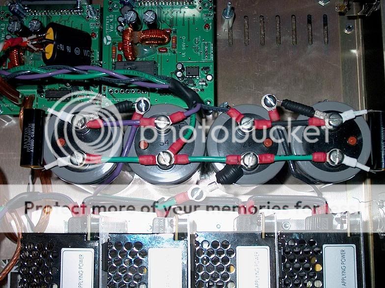
Well,..... about hooking up the UcDs, I'm getting close to an experimental setup using the tweaked SMPS and 2 UcDs for the woofers. Originally I planned to use two UcD400s for the two woofers per channel, either in bridge or each woofer an UcD. I now plan to first do a test run with two modules, one for each channel, so each UcD driving two woofers. With this super stable tweaked SMPS (with all those caps, actually plan to use even more than I showed before and also plan to add ELNA Cerafines close to the modules themselves). Just to be sure
and I have payed a lot of money for those ELNAs so they have to be used.Hopefully I get to that in the weekend.
And then, I can't wait starting modding the UcD400. I have already removed the input caps and have replaced the caps for the opamp supply with 22uF BG caps. Nothing else done yet. Plan to later try to replace the 470uF caps with something bigger and lower series resistance. Want to do measurements on the supply rails (inside the module, so after the onboard inductors) to see whether other caps make the rails more silent.
This is going to be a loooooooooooong project, but it is lots of fun.
Best regards
Gertjan
Hello all.
Ghemink, you seem to have gained a lot of experience with your modification to the A&T labs supply.
I have just put my DIY SMPS to work. It is a half-bridge, with ETD44 transformer, intended for +/-60V at 600-800W.
By the moment I have only tested at up to 450W for several seconds and seem to run quite cool. Let's see when I leave it that way for hours!
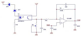
I also use a SG3525 control IC, and my feedback is implemented as in the attached schematics. My concern is what happens with light loads. I don't know if the compensation is ok as it is now, but it produces a strange ripple (and even some noise) when output current is below, say, 100w.
What can I do to improve no-load (or very light load) behaviour while preserving fast enough transient response?
Thanks!
Ghemink, you seem to have gained a lot of experience with your modification to the A&T labs supply.
I have just put my DIY SMPS to work. It is a half-bridge, with ETD44 transformer, intended for +/-60V at 600-800W.
By the moment I have only tested at up to 450W for several seconds and seem to run quite cool. Let's see when I leave it that way for hours!
I also use a SG3525 control IC, and my feedback is implemented as in the attached schematics. My concern is what happens with light loads. I don't know if the compensation is ok as it is now, but it produces a strange ripple (and even some noise) when output current is below, say, 100w.
What can I do to improve no-load (or very light load) behaviour while preserving fast enough transient response?
Thanks!
Attachments
Pierre said:Hello all.
Ghemink, you seem to have gained a lot of experience with your modification to the A&T labs supply.
I have just put my DIY SMPS to work. It is a half-bridge, with ETD44 transformer, intended for +/-60V at 600-800W.
By the moment I have only tested at up to 450W for several seconds and seem to run quite cool. Let's see when I leave it that way for hours!
I also use a SG3525 control IC, and my feedback is implemented as in the attached schematics. My concern is what happens with light loads. I don't know if the compensation is ok as it is now, but it produces a strange ripple (and even some noise) when output current is below, say, 100w.
What can I do to improve no-load (or very light load) behaviour while preserving fast enough transient response?
Thanks!
I don't think I can help you here. The feedback loop of the A&T labs supply is completely different. I remember however that with very light or no load, that supply also behaved a bit strange. However, a load of 100-200mA of a few amps connected is already enough to make it behave OK. So I have no issue.
Maybe others have some tips?
Best regards
Gertjan
I'm in the middle of my first amp project using an SMPS supply and I have also experienced some very strange behavior from the supply.
After connecting the capacitor bank the supply makes some very strange noises.
I have found two ways to remedy this, neither of them I really like. I either have to put a load of 10w or greater on the supply, or put a very low value resistor in series before the caps. I have opted for the second choice for now, as 10w dissipated from a resistor feels a lot hotter than one would assume.
I'm using some DIY wire wound resistors of about 0.3ohms. This causes a voltage drop of <1v at full power, but I will rarely ever play the system at full power. Putting the resistors on the +- rails got rid of the noise at idle, but I also had to put one in series with the ground or the supply would make yet another strange noise if the amp played any frequency under 60Hz or so.
Even if I decided to use the 10w dummy load instead of the resistors in series with the rails, I still needed the one in series with ground or I would get the noise with low frequencies.
I really wanted to us an SMPS in this project, but if I had it to do over again I think I would just use a trafo .
.
After connecting the capacitor bank the supply makes some very strange noises.
I have found two ways to remedy this, neither of them I really like. I either have to put a load of 10w or greater on the supply, or put a very low value resistor in series before the caps. I have opted for the second choice for now, as 10w dissipated from a resistor feels a lot hotter than one would assume.
I'm using some DIY wire wound resistors of about 0.3ohms. This causes a voltage drop of <1v at full power, but I will rarely ever play the system at full power. Putting the resistors on the +- rails got rid of the noise at idle, but I also had to put one in series with the ground or the supply would make yet another strange noise if the amp played any frequency under 60Hz or so.
Even if I decided to use the 10w dummy load instead of the resistors in series with the rails, I still needed the one in series with ground or I would get the noise with low frequencies.
I really wanted to us an SMPS in this project, but if I had it to do over again I think I would just use a trafo
.
theAnonymous1 said:I'm in the middle of my first amp project using an SMPS supply and I have also experienced some very strange behavior from the supply.
After connecting the capacitor bank the supply makes some very strange noises.
I have found two ways to remedy this, neither of them I really like. I either have to put a load of 10w or greater on the supply, or put a very low value resistor in series before the caps. I have opted for the second choice for now, as 10w dissipated from a resistor feels a lot hotter than one would assume.
I'm using some DIY wire wound resistors of about 0.3ohms. This causes a voltage drop of <1v at full power, but I will rarely ever play the system at full power. Putting the resistors on the +- rails got rid of the noise at idle, but I also had to put one in series with the ground or the supply would make yet another strange noise if the amp played any frequency under 60Hz or so.
Even if I decided to use the 10w dummy load instead of the resistors in series with the rails, I still needed the one in series with ground or I would get the noise with low frequencies.
I really wanted to us an SMPS in this project, but if I had it to do over again I think I would just use a trafo
Adding a capacitor bank to a SMPS may need a modification of the feedback network in the SMPS to keep the feedback loop stable. By adding a resistive load at the output or a resistor in the rails before the caps, you change the frequency/phase response of the system and thus the feedback loop may become stable. When adding caps, you need to reconsider the feedback loop such as changing the position of poles/zeros in the feedback network. I did that for my SMPS and got very good results.
Best regards
Gertjan
Pierre said:Thanks for the replies.
Gertjan, how did you calculate the right position of zeroes/poles for the new capacitance value?
What symptoms did you notice when you added a lot of capacitance after the supply beforet touching the fb network?
Best regads
Hi Pierre,
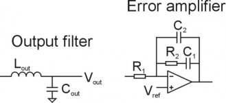
With extra caps, the SMPS became unstable under some conditions. The reason is that the compensation network in the feedback network (error amplifier) is designed for a certain output filter. The output filter in the SMPS should consist of an LC network (see attached figure). The error amplifier in the feedback loop may look like the one in my attachment. If that is the case, then if you increase Cout by adding caps, you have to increase C1 of the error amplifier circuit. If you increase the Cout value with a factor x, than C1 should be increased by a factor sqrt(x) to be sure that things stay stable. This would be a conservative and safe approach.
However, one can get more out of it. when Cout is increased, the Q factor of the LC output filter becomes lower, this allows us to increase the gain of the error amp by increasing R2. Of course, if that is overdone, the SMPS becomes unstable again. Adding caps and increasing the gain is very beneficial as it would reduce the output ripple of the SMPS strongly. I tried all this in my SMPS and it works great.
Good luck
Gertjan
Attachments
ghemink your feedback network is a so called PI (proportional, integral) control network. C1 and C2 works as integrators. This removes the steady state error, but also increses the Q factor af the closed loop. If these capasitors becomes to small the loop will become unstable.
You can however add much more integrating feedback (smaller capasitors) without causing the loop to become unstable, just adding a derivitive in your feedback loop. This kind of control is called PID and is used a lot in control systems. I'm using it in my Class D designs. You can do this by placing a capasitor parallel with R1. To limit the current you should actually use a capasitor in series with a resistor (500ohm or someting like that).
You can however add much more integrating feedback (smaller capasitors) without causing the loop to become unstable, just adding a derivitive in your feedback loop. This kind of control is called PID and is used a lot in control systems. I'm using it in my Class D designs. You can do this by placing a capasitor parallel with R1. To limit the current you should actually use a capasitor in series with a resistor (500ohm or someting like that).
Thank you for explaining that to me ghemink, now I know "why" the supply reacted the way it did by just adding more capacitance.
I have no SMPS experience and my supply is actually just 4 off the shelf SMPS's in series, so finding and modifying the feedback loop would probably be close to impossible for me to do.
I have no SMPS experience and my supply is actually just 4 off the shelf SMPS's in series, so finding and modifying the feedback loop would probably be close to impossible for me to do.
sovadk said:ghemink your feedback network is a so called PI (proportional, integral) control network. C1 and C2 works as integrators. This removes the steady state error, but also increses the Q factor af the closed loop. If these capasitors becomes to small the loop will become unstable.
You can however add much more integrating feedback (smaller capasitors) without causing the loop to become unstable, just adding a derivitive in your feedback loop. This kind of control is called PID and is used a lot in control systems. I'm using it in my Class D designs. You can do this by placing a capasitor parallel with R1. To limit the current you should actually use a capasitor in series with a resistor (500ohm or someting like that).
Hi Sovadk,
Thanks for the remarks.
Yes, I know it is a PI network, the SMPS came default with that network and I modified it increasing the cap and also increasing the gain. I know the theory (at least some of it) of PID but in case of a lot of additional caps in the LC filter, the Q-factor of the LC filter becomes very low so that it starts to approximate a 6dB drop off instead of 12dB with a higher Q-factor. With a high Q-factor output filter, PID is probably the best solution to get a good phase margin, but for a low Q roll-off it does not work well. I actually tried a PID configuration but quickly dropped it after I realized that the Q-factor of my modified LC filter is too low for a PID configuration, it can become unstable (it actually did). If you make the 2nd cap smaller, the phase margin with PID can be improved, but then the gain at high frequencies becomes very high and I did not like that as the whole thing may become more sensitive to noise.
On top of that, the extra caps that I hooked up at the output of the SMPS are connected in a T configuration with R-C-R and R=0.1Ohm and a couple of those RCRs in parallel. This lowers the Q-factor of the LC filter even more so that I get a very smooth 6dB roll-off and get very stable operation with the PI network while I can increase the gain as well. For a supply for audio use, I like to have smooth behavior and this works great.
Best regards
Gertjan
theAnonymous1 said:Thank you for explaining that to me ghemink, now I know "why" the supply reacted the way it did by just adding more capacitance.
I have no SMPS experience and my supply is actually just 4 off the shelf SMPS's in series, so finding and modifying the feedback loop would probably be close to impossible for me to do.
Wow, 4 of them in series, that will be complicated from a regulation point of view, I think they could start influencing eachother which may give strange effects as well. For your case adding a resistors in series with the output caps as you say is working to a certain extent since it modifies the roll-of slope of the LC filter. From a certain frequency on (depending on the R and C value), the LC filter will become 1st order instead of 2nd order without R. Then the phase margin is larger and the SMPS becomes stable. In reality, all SMPS LC filters become 1st order at some frequency due to the internal series resistance that every capacitor has.
My only advice for now (if you can`t modify the feedback loop) is to use a series resistor with your output caps. This will give you some voltage drop at high load but probably less than what you would have had with a normal transformer.
Anyway, using an SMPS for audio applications is not straightforward, when adding caps, one has to be prepared to modify the SMPS to keep things stable. I have thought on going back to a simple tranformer but I like the regulation of the SMPS and it gives me a very solid and stable voltage with very low 50Hz/100Hz ripple.
Best regards
Gertjan
It's right that you can change the Q factor of the open loop by increesing the output capasitors (Q=sqrt(L/C)/R), but then roll off freauency change too, which you have to conpensate for. f0_LC=1/(2*Pi*sqrt(L*C)) has to follow the poles of the feedback network where f0_RC=1/(2*Pi*R*C). Therefore sqrt(L*C)=constant*R*C should be fulfil (the LHS is LC filter values and the RHS is feedback network values). As stated earlier, if you only choose to change capasitor values sqrt(C)=constant*C.
If you tune your pid control, you can make the closed loop slope a 1 order (including the LC filter) with a Q factor of 0.7. This will be independent of the Q factor of the output filter.
If you tune your pid control, you can make the closed loop slope a 1 order (including the LC filter) with a Q factor of 0.7. This will be independent of the Q factor of the output filter.
A LC filter will always have a phase shift of -180 degrees and will cause instalillity of osccilation if the gain in a closed loop is close to unity at this -180 degree freqyency. If the Q factor is large, then the -180 degree frequency will be the same as the roll off frequency of the filter. If the Q value is smaller then the phase shift will reach -180 degrees at a higher frequency. The point is that It'll will always reach -180 degrees.
A differential network will give you +90 degrees of phase shift and give you a 1order rising amplitude slope. Adding such a network after the LC filter, will reduce it to a first order (-180+90 degrees=-90), which will always be stable in a closed loop.
The SMPS here is not a special case. PID control is possible and will work much better than a PI controller. A PI controller removes steady state errors but increese instability.
I've attached a schematic of the PID controller I'm using in my Class D design. I've got the abillity to add 20dB more feedback at 10kHz and increese stability by adding R53 and C24 to the feedback network. I've found the values by trail and error in pspice.
Attachments
Anyway, using an SMPS for audio applications is not straightforward, when adding caps, one has to be prepared to modify the SMPS to keep things stable. I have thought on going back to a simple transformer but I like the regulation of the SMPS and it gives me a very solid and stable voltage with very low 50Hz/100Hz ripple.
I mainly chose to use SMPS over a transformer because of the regulation and also because I purchased all four of them for the same price of a good toroid.
My final solution for my stability issue is 0.1ohm resistors in series with +- and ground, and an 880ohm dummy load that draws 3.5 watts placed across the rails.
Using a 600 watt load of halogen lights, the voltage drop is less than 1v, better than a trafo would do I guess. The 3.5 watts of heat from the dummy load is much more reasonable than the 10 watts from before, so I'm happy with my fix for now.
There doesn't seem to be any other problems with the setup, it works perfect from low volume all the way to full power now with no more strange clicking and tickings from the supply.
Another benefit of the dummy load is it helps discharge the 130,000uf of capacitance after I turn the amp off.
- Status
- This old topic is closed. If you want to reopen this topic, contact a moderator using the "Report Post" button.
- Home
- Amplifiers
- Class D
- A and T labs K6 SMPS for Class D amp use