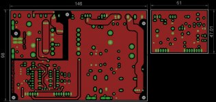
That will not work, it will blow up in your face because the gate driver is a mile away from the switching fets, even if its only a 20kHz smps, the IR2110 needs to be as close to the fets as physically possible.
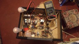
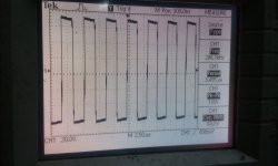
i will post pictures of the smps working soon
thanks tekko. i have etched three boards i will loop a wire to the power of the i.c's . also make the correction and post the revised version.
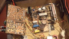
the smps is based on the one i previously made and is working well to date. i changed because i needed simplicity in mounting.
the previous version >>>>>>
the smps is based on the one i previously made and is working well to date. i changed because i needed simplicity in mounting.
the previous version >>>>>>
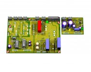
the pictures
Attachments
-
 DSC01180.jpg614.3 KB · Views: 1,165
 -
 DSC01441-Optimized-1.jpg213.6 KB · Views: 1,043
 -
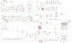 smps half bridge 740 schematic.jpg327.5 KB · Views: 587
 -
 smps half bridge 740 pcb top side.jpg218.8 KB · Views: 366
 -
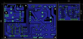 smps half bridge 740 pcb bottom side.jpg238.3 KB · Views: 933
 -
 smps half bridge 740.jpg270.9 KB · Views: 982
 -
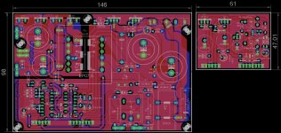 smps half bridge 740 fullview.jpg340 KB · Views: 1,010
 -
smps half bridge 740 components full .pdf45.9 KB · Views: 704
-
smps half bridge 740 schematic.pdf46.6 KB · Views: 431
-
smps half bridge 740 pcb main board all art work full.pdf280.8 KB · Views: 464
Last edited:

The major disadvantage with pre filter feedback: Frequency response is only flat for one speaker impedance, say if you design the output filter for 8 ohms, then at 4 ohms it will roll off early, cutting down on the highs.
Respectively if you design it for 4 ohms, then at 8 ohms you get a nasty peak in the 10-20kHz.
For this reason i would only use pre filter feedback in like active monitors/boomboxes where the speaker impedance never change.
For a general purpose amplifier such as a standalone amp used with many different speakers throughout its life(2-16 ohms), i would only use post filter feedback to make the amp virtually load invariant, much like a class ab amp.
My post filter feedback class d is stone cold or ever so slightly warm, heating has nothing to do with pre/post filter feedback, its all deadtime.
And noise is layout related, having power input on one end of the board and audio input on the other is just begging for noise(read the hypex white papers on layout and such), the audio ground return has to pass through high current HF ground paths around the mosfets and the capacitors to the rails.
Well technically you could have the audio input on the opposite end of the board to the power inputs and speaker output, but only if you ran a completely separate audio ground trace on the enge of the board to the center point between the onboard filter caps and have the other grounds separate.
But some ppl prefer to have the distortion the output filter creates by omitting it from the feedback loop because it sounds better to them(I can certainly not hear a difference though as i've built low power pre filter class d with just as good sound quality as my current UcD based class d) LC Audio states on their site, post filter feedback has a "rubber band" sounding bass, though i have no clue what that would sound like as my UcD bass sound just like the bass from a class ab amp.
thanks again tekko for sharing. real powerfull information.
how can one separate the grounds, to reduce noise?
I usually separate power supply ground, audio ground and output transistor grounds and join them once at a star point usually at an edge connector.
I also return from the speaker to the centre of the smoothing capacitors.
I designed a audio mixer and ignored star grounds and the hum was massive.
I redesigned the pcb separating audio ground and power supply ground and joining it only once at edge connector and there was almost zero hum.
What can happen is the charging pulses into the smoothing capacitors modulate the ground line and inject noise into the audio.
hello,manojtm i already build your AUD600 VER3,after a couple of hour playing minimal audio my 10N20 12v bias regulator heat's up,my working voltage +/- 56vdc,any possible solution?thank's a lot(Fsw=195khz)
Hi don2007,
it will warm, use heat-sink. no problem found in +/-75V supply rails
Regards
MANOJ
The major disadvantage with pre filter feedback: Frequency response is only flat for one speaker impedance, say if you design the output filter for 8 ohms, then at 4 ohms it will roll off early, cutting down on the highs.
Respectively if you design it for 4 ohms, then at 8 ohms you get a nasty peak in the 10-20kHz.
Hi tekko,
In class D design there is no major difference in pre or post filter feedback
In class d you must change filter for 8,6,4 & 2 ohms speaker,Otherwise cutoff freq will change.
best result will give 18uH or 22uH coil for 8,6 & 4 ohms
Regards
MANOJ
I usually separate power supply ground, audio ground and output transistor grounds and join them once at a star point usually at an edge connector.
I also return from the speaker to the centre of the smoothing capacitors.
I designed a audio mixer and ignored star grounds and the hum was massive.
I redesigned the pcb separating audio ground and power supply ground and joining it only once at edge connector and there was almost zero hum.
What can happen is the charging pulses into the smoothing capacitors modulate the ground line and inject noise into the audio.
pls can you draw a simple block diagram to illustrate .
1/ Join all the audio ground together.
2/ Join all the power supply grounds together.
Take track from the audio ground to the edge connector where ground comes in.
This now the star ground point.
Take a track from the power supply ground to the same point.
Words explain it better than a picture.
I have used this technique on 4 audio systems now and never had a hum problem.
- Home
- Amplifiers
- Class D
- My class D amp