Hi all class D fans. Is there any audibly difference between PWM circuits using triangle or sawtooth PWM generators? Which is best between them? I made my self design and use triangle because it easiest to generate. But what about sounding results?
Best regards. Thanks in advance.
Best regards. Thanks in advance.
Yes, I agree. But I see somewhere in the web some pdf´s that uses the sawtooth as PWM input to the comparator.
Hmm... that's odd, I wonder why?
For an accurate PWM signal you'd want as symmetrical and pure a triangle wave as you could get. Feeding a nice clean square wave into an opamp integrator will produce a good triangle wave if you chose your components carefully (low temp drift caps and resistors, good layout and the rest).
Check this out, this is kind of neat - it's how to make a triangle wave with 2 opamps and some passives. It also talks about integrators:
Generating Triangle Waves
Jim
I suppose the comparator of the Triangle/Sawtooth and the input signal is where the trouble is likely to be.
A triangle wave will give you a symmetrical center aligned PWM, for any given instant in the signal.Controlling the deadtimes becomes easier. Similarly checking for cross- conduction and even splitting up the waveform for a full/half bridge topology.
But with ramp the instant when the wave reaches its peak and goes to 0 is critical.
If the ramp is too slow you have cross conduction in a mosfets if it is too fast the comparator wont switch states to signify the end of the pulse.
It can be done, but takes too much effort to design it safe.
In a circuit of my own, I use an HCF4047 as a free running 500KHz oscillator, and take the output from pin 10 & 11 (complementary), and feed them an integrator using a CMOS opamp like TS274 used as double integrator, this means, integrating not only inverting input, but also non inverting, to ground. It gives a nice triangle wave.
The trouble in my two early projects is the same. I used the principles exposed in fig 5 of:
http://users.ece.gatech.edu/mleach/ece4435/f01/ClassD2.pdf
But sometimes, it doesn´t start because of "CF" gets some charge greater than (positive or negative related to ground) the triangle wave and the comparator becomes blocked. Had anybody tried that system?
those self-oscillating circuits suffer from thermal drift - maybe it's not important to your design.
I chose to drive mine with an oscillator - stable always.
Watch out for DC drift on the opamp integrators. Also, depending on the frequency you run it at, the opamps require high slew-rate. When the triangle changes from ramp up to ramp down, a slow opamp will do some really bizarre stuff. So, either use a better part, or setup your comparator that stays away from the junky transitional spot.
Triangle
The Oscillator is independent, and made with an HCF4047, and is stable and 50% warranted outputs at pin 10 & 11, and the integrator is AC coupled, and I put some 10Mohm in parallel with integrating caps, so DC drift is un-measurable since CMOS OpAMP has extremely low DC input bias current. The trouble appears with the integrator "decoding" the output PWM, and comparing with input signal. The audio quality is reasonable good for a first approach. But the truble is the block effect.
Self oscillating is unlike for me, people that has tryied them tells that not only frequency drifts, it is also very "QRM" generator.
I will do a schematic to post in following times.
Thanks for replies and suggestions.
I will do a schematic to post in following times.
This should have been the first, because the principle on figure 5 is free of lockout. The problem is in your implementation.
There is a good chance that the locking is caused by the phase reversal issue as highlighted by Nigel.
Basically it can happen on OP amps and comparators as well, but most modern comparators are internally protected against this issue.
Such phase reversal can happen at high common mode input voltages and also at high differential input voltages.
In case your circuit suffers from phase reversal, then global feedback loop will change from negative feedback to positive feedback and the system will lock.
Here a nice description about phase reversal in OP amps.
http://www.analog.com/static/imported-files/tutorials/MT-036.pdf
It appears to me that blocking occurs when shut down the amp with no load. Shorting temporarily the capacitor above mentioned, and it stats working pretty fine. I´m thinking in putting a 4066 with a RC time constant and short these caps a couple of millisecond before starting the PWM signal.
Thanks for the replies.
Thanks for the replies.
and is stable and 50% warranted outputs at pin 10 & 11, and the integrator is AC coupled, and I put some 10Mohm in parallel with integrating caps, so DC drift is un-measurable since CMOS OpAMP
Any deviation from 50.0% duty cycle will *eventually* cause DC drift on the integrator. I don't think those 10M resistors will help since you are driving the integrator at all times. I dealt with the drift problem using a servo loop.
Any deviation from 50.0% duty cycle will *eventually* cause DC drift on the integrator. I don't think those 10M resistors will help since you are driving the integrator at all times. I dealt with the drift problem using a servo loop.
That integrator is not a real integrator, only at high freq! At low freq it's differentiator, 0 DC gain:
AC coupled, and I put some 10Mohm in parallel with integrating caps
But we still don't know the complete schematic, so any further discussion is pointless. The problem surely comes from the unseen parts.
I am not sure if my point is clear, so here is an example.
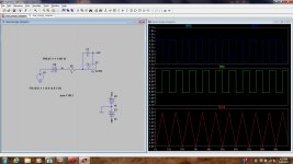
Each circuit is an ideal integrator, triangle wave generator. The driver is a square wave. Time constant is 1 second. V4 is present only to setup initial conditions for the simulation.
In the 50% duty cycle version, the triangle looks really good. There is no DC drift.
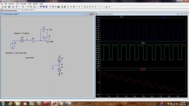
Now look at the other picture. Here, I set the duty cycle to 40%. See how the DC level drifts away? That's bad. In a real opamp, when the drift hits the supply rail, the circuit stops working. This is why I said you must maintain 50.0% duty cycle. You will find that it is unlikely to get parts that are precisely 50.0% duty cycle.
Each circuit is an ideal integrator, triangle wave generator. The driver is a square wave. Time constant is 1 second. V4 is present only to setup initial conditions for the simulation.
In the 50% duty cycle version, the triangle looks really good. There is no DC drift.
Now look at the other picture. Here, I set the duty cycle to 40%. See how the DC level drifts away? That's bad. In a real opamp, when the drift hits the supply rail, the circuit stops working. This is why I said you must maintain 50.0% duty cycle. You will find that it is unlikely to get parts that are precisely 50.0% duty cycle.
Attachments
Now look at the other picture. Here, I set the duty cycle to 40%. See how the DC level drifts away?
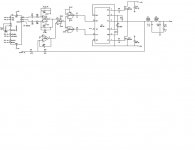
That´s the reason why the integrator is AC coupled to the oscillator (HCF4047) and is closed loop to DC with high ohmic value resistors (2.2M)
The cap that sometimes becomes blocking the amp is the marked as C6, and related to U2, the main op amp that acts as a AC and DC servo. But, this fault occurs when no load, and switch on / off the circuit, apparently with load this doesn´t happens.
- Status
- This old topic is closed. If you want to reopen this topic, contact a moderator using the "Report Post" button.
- Home
- Amplifiers
- Class D
- Class D: Triangle or Sawtooth?