The picture is horrible, many characters are unreadable. You must be able to do much better.
Problematic part can be the AC coupled gate driver input (quite bad solution), and/or the bootstrap supply of gate driver IC.
C6 is innocent! He tries to eliminate the error, but the following stages can't react.
Problematic part can be the AC coupled gate driver input (quite bad solution), and/or the bootstrap supply of gate driver IC.
C6 is innocent! He tries to eliminate the error, but the following stages can't react.
Finally, this is my circuit:
Some comments:
1. The triangle wave generator looks odd. You drive it differentially, but I don't think it is going to work as you expect. The non-inverting node on that opamp is going to see a non-zero voltage. In fact, it'll be an RC shaped thingy. It looks like you wanted to make it symmetrical, but it's not. The non-inverting leg will have a constant current, normally, if it is working correctly and the voltage at the output is the linear product of the constant-current, the constant voltage applies, and the time-constant. You might try just grounding the non-inverting side. You still face DC drift is not 50.0% duty cycle.
2. You've got HIN and LIN pins AC coupled. They need to be referenced to the negative rail of 2110. As it is drawn, they float. This is often done with a level shift circuit. Your -Rail is -12V.
3. VCC supply is missing from the 2110, oversight?
4. The feedback point is going to be either +12V, or -12V. I don't think that's right. You need the audio portion for feedback; so either take it from the speaker side or maybe R-C filter it to get the audio only.
5. Not sure if that C6 is your problem or not. The time constant is somewhat important so that the opamp does not go to a rail at initial conditions, but really what is wrong is what I said in (4).
The picture is horrible, many characters are unreadable. You must be able to do much better.
Problematic part can be the AC coupled gate driver input (quite bad solution), and/or the bootstrap supply of gate driver IC.
C6 is innocent! He tries to eliminate the error, but the following stages can't react.
Yes, it is horrible, and I´m currently trying to get a more fine pic.
Thanks for the ideas. In respect to the triangle, it is my own idea, and the output saw with an oscilloscope looks pretty fine.
The trouble is that C6 maintain the opamp blocked after working without load, but I believe it can be because of the output stage when the IR2110 and FET´s has no load, and then the last pulse has the returned pulse (fly back) from the first coil of the filter. I´ll continue improving the images. Be patience.
No matter what makes C6 to reach the limit, it would have come to the normal range if the following stages worked!
There are some possible reasons why the following stages can't react. The most probable is the AC coupled gate-driver input.
There is a workaround to your problem, limiting the voltage on C6 to less than the amplitude of triangle, by 2 zener diodes. But this has some unpleasant sideffects, and basically the wrong stage is not this.
Feedback is OK, triangle is OK, phase slitter too, etc...
Feedback is OK, triangle is OK, phase slitter too, etc...
Nope, the feedback is not okay. The feedback has to be audio frequency, not carrier frequency. He is feeding back either V+ or V-, depending which output transistor is on.
I haven't checked, but the polarity is also important. The opamp is setup such that the D-Amp *must* be inverting. If not, the opamp has no chance of working.
Maybe you should get the D-Amp working first before applying global feedback? Remove R10, Replace C6 with resistor, same value as R9. Now there is no feedback, the D-Amp will run in open loop so gain is going to be large.
Hey - just noticed your gain is set to R10/R9 = 47k / 478 = 100 (close enough). Your rails are +/- 12V, so the biggest input signal that would work (assuming the circuit is doing the right thing - which it is not) is +/- 0.12V
I recommend getting it to run with the input grounded, so that the output expected voltage is 0.0 Volts.
Lot's of stuff to fix
The feedback has to be audio frequency, not carrier frequency.
PWM signal contains audio band too. Therefore feeding back PWM is perfectly OK! Proven in many thousand designs.
He is feeding back either V+ or V-, depending which output transistor is on.
This is called pre-filter feedback, and known by everybody who knows the littlest about ClassD audio. Don't burn yourself! This is the second lession in ClassD audio.
No problem as long as loop gain cutoff frequency is less than half of the carrier freq.
I haven't checked, but the polarity is also important. The opamp is setup such that the D-Amp *must* be inverting. If not, the opamp has no chance of working.
Don't think others are idiot! Everybody knows what is negative feedback. Of course the amp is inverting. It basically WORKS, just doesn't start always! Which thread do you read? Apparently not this one!
I recommend getting it to run with the input grounded, so that the output expected voltage is 0.0 Volts.
With opened input the expected output voltage is much more precisely 0!
Don't think others are idiot!
wow - that's cruel.
I was only trying to help - so good luck to you
And here we have an AC coupled feedback loop.
Not really. AC coupling of PWM signal does carry DC information, as long as duty cycle is more than 0 and less then 100 %.
And that AC coupling is not exactly AC coupling, because input of the IR2110 contains a clamping diode to GND, which restores the bottom of the PWM pulses (therefore automatically restores the rising edge of the next pulse). (In analog base-band video signal transmission the same trick is done. It can be AC coupled, still the DC can be restored, it works amasingly good!)
The problem is the fact that at start the duty cycle can reach 0 or 100 %. Only at this state the feedback loop breaks. (Or during a long overload. But then the next cycle can turn back the amp.)
Last edited:
Without that the circuit is begging for phase reversal of U2.
Maybe, if signal source is AC coupled and there is no output load (or AC coupled). Otherwise there can't be such high voltage. Any of the terminals pulls down the inverting input near 0 during non-operation if there is a conductance.
For more confident error analysis more info would be fine. Readable part types, description of input, output, measured voltages on output of U2, phase splitter, then maybe others.
Last edited:
Even if the input is theoretically DC coupled you cannot ensure a low drive impedance all the time. Especially when turning OFF/ON the entire stereo system there is a high likelihood for undefined conditions.
But yes, remote debugging is unreliable. You never get the information you would like to have.
Trying simple mods based on an educated guess is a promising approach, even if not the most scientific.
But yes, remote debugging is unreliable. You never get the information you would like to have.
Trying simple mods based on an educated guess is a promising approach, even if not the most scientific.
Even if the input is theoretically DC coupled you cannot ensure a low drive impedance all the time.
As I said "if signal source is AC coupled and there is no output load (or AC coupled)"
And no low drive impedance is needed, just any conductance.
And I didn't say there is low enough impedance, just pointed out the 2 conditions needed for phase reversal at U2.
Especially when turning OFF/ON the entire stereo system there is a high likelihood for undefined conditions.
Yes they are undefined (sadly), but we can choose a likely explanation instead of a less likely. Somebody complaining about a non-working amplifier while there is no input and no load? I guess not.
I chose a more likely explanation of non-operation, which is based on only the known facts and 1 very probable assumption (supply voltage builds up gradually, relative slowly, therefore gate-driver starts at (off, off) input state).
Last edited:
(supply voltage builds up gradually, relative slowly, therefore gate-driver starts at (off, off) input state).
Definitely also a valid theory.
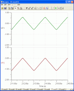
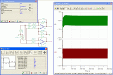
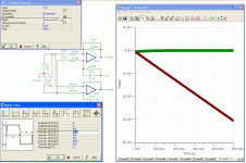
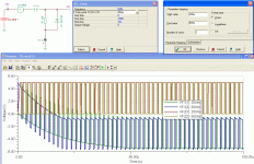
The results of the simulation. I reduced the additional elements (10n, 2M2) to achieve shorter settling time, otherwise the simulation lasted too long.
The triangle is little round because I've set 100 ns rise/fall time.
The triangle is little round because I've set 100 ns rise/fall time.
Attachments
As far as the triangle oscillator goes, if the analysis is based on the single ended flavor (presumably the differential version is similar) then the output is not really triangle - it's exponential.
I am ignoring the DC blocking caps on the input because they represent only a small offset at 500 kHz, compared with the 10K input resistor.
There is more than one way to do this but, for an inverting opamp, V1=V2 and in this example, V1 is grounded (0 volts)
Vo(t) = -i(s) * Z(s)
where
i(s) = Vin(s) / R1
Zf = R2 || C
Zf = R2 / (S*R2*C) (in Laplace)
let a = 1/R2*C and plug it into the Zf
Zf = 1/C * [1/(S+a)]
Vo(s) = [-Vin(s) / R1] * [1/C *[1/(S+a)]]
Vo(s) = [-Vin(S) / (R1*C1)] * [1/(S+a)]
a little reverse lookup, and you find the equation in the time-domain is
V(t) = -Vin(t) / (R1*C1) * e^-t/(R2*C)
Mathematically speaking, this is an exponential rise/fall output (depending if the drive is + or -). The reason the simulation, and real-life appears triangular is because over a short enough time, the curvature is not visible. I tried it in simulator to satisfy my curiosity (exaggerate the period, like 10 seconds on, 20 seconds off) - but have not posted it yet.
An integrator circuit with just the capacitor is a true ramp. That equation is
Vo = -Vin/RC * dT (not going to derive it here). Mathematically, this is truly a straight line ramp up and down.
As a boy said, the AC coupling is made with a DC restorer internally at the IR input. This idea is for easily modify the power output from the amplifier, with the only expedient of changing the power handling capability of the devices (increase or decrease current) if needed (possibly not with IRF510), and the supply itself. There is a non draw piece of the schematic, and is the power supply. It is a SMPS (Flyback giving from +-12 to +-24V) and isolated secondaries post regulated for the sawtooth generator, and the low side of the IR2110/MOSFET bootstrapping (12/15V).
I apologize by the heated discussions, That wasn´t the object of my thread.
The sawtooth as can be said in an oscilloscope is almost perfect, only some ringing in the angles, but I know that is from not well bypassed power supplies, in an previous protoboard it also happened, and when properly wired, it disappeared. Also I am sure that sawtooth generation ISN´T my trouble. It is in the negative feedback integrator the real trouble. But It appears sporadically.
Thanks to all replies.
Osvaldo.
Last edited:
- Status
- This old topic is closed. If you want to reopen this topic, contact a moderator using the "Report Post" button.
- Home
- Amplifiers
- Class D
- Class D: Triangle or Sawtooth?


 Guys you need to cool it, infractions issued, and if the aggressive discussion continues I will close the thread. Attack ideas, keep the personal out of it! You have been warned.