Your amplifier is so clean because it's not really clipping.
Evita,
Control your frustation

My amp[basically with a clocked modulator frontend] is very well clipping as one can see the waveforms in my post.
But don't let me keep you from marketing your "prototype"
or "your" self oscillating concept
Cheers!!!
Last edited:
Evita,
Control your frustation
My amp[basically with a clocked modulator frontend] is very well clipping as one can see the waveforms in my post.
But don't let me keep you from marketing your "prototype"
or "your" self oscillating concept
Cheers!!!
Oh, don't worry, small quantities of these prototypes are already in the powered speaker US market, it has far more advantages than disadvantages, some customers think that it outperforms many rack mount amplifiers. You are just persuading me to add a pre-clipper like yours in the next PCB revision, which I'm about to finish, and make it even better
The modulator itself is probably the oldest part of the design, it calls for an update. I have also discovered slight overshoot in the square wave response that I want to get rid of. This thread motivated me to do many performance tests. My will to offer the best performance is at least as strong as yours
Last edited:
You are just persuading me to add a pre-clipper like yours in the next PCB revision, which I'm about to finish, and make it even better
You know grapes tend to become sour when you cant reach for grapes.................
Keep saying it as pre clipper[Since you are unable to figure out what exactly i use to get clean clipping ], as it will help you alot
Adios!!!
Last edited:
Non-linear elements in the feedback loop.
Evita,
Looks like you're *limited*
Well, isn't it more interesting on how does the amp behave BEFORE it clips?
Clean clipping isn't that hard unless you go for higher post-filter feedback, like 20dB@20kHz.
Nothing wrong in pre-clipping and letting some stages stay below clip level...
The signel is already spolied anyway.
Clean clipping isn't that hard unless you go for higher post-filter feedback, like 20dB@20kHz.
Nothing wrong in pre-clipping and letting some stages stay below clip level...
The signel is already spolied anyway.
Clipping recovery behavior tells a lot about amplifier transient response. If the loop has poor stability, it will become evident at first glance by looking at 1khz clipped sine. Square wave test provides the same information but at the expense of increased amplifier stress.
Figure out the intentions behind the will to hide clipping behavior.
Figure out the intentions behind the will to hide clipping behavior.
As Eva said, non-linear element in feedback loop work well to achieved good transient response...Other way is to have small gain switching amp with hight voltage swing front end...No need to pre-clip anything with booth option.
I am going to try an analog switch in feedback path, which turns a global prop-integrator feedback into low feedback proportional whenever internal overload (slew overload, clipping, overcurrent etc.) is detected.
The diodes/zeners in feedback path always degrade THD before clipping in my scheme.
The diodes/zeners in feedback path always degrade THD before clipping in my scheme.
Try to use transistors, like Eva does
They can provide more sharp threshold and if tuned properly will start to work exactly before clipping......good portion of our classD Kings/Queen in this thread here, but I am missing your will to tell anything.
I think there is no doubt that good clipping behavior is no big deal at feedback levels around 20db-30db also for post filter feedbacks.
The entire discussion is not worth much with out the following informations.
-Feedback structure: Post filter, pre filter, mixed.
-Feedback characteristic: PID etc.. , or even better a simplified drawing.
-Amount of feedback depending on frequency.
-Clipping method: Natural clipping, pre clipper, non linear feedback, reducing forward gain at higher output levels , ....?....
-Clocked / self resonant
I will make the start with two of my oldies:
My current design approaches are simply not ready yet and still just
on the level of simulations.... so I hope you are not bored by my old stuff.
It is just an example of how I would love to see you turning your comments into a technical discussion.
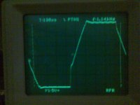
1. A low feedback solution, providing approx. 30db feedback over the entire audio range. Well 30db in the shown load case (clipping into 2R5), which makes the weak supply sagging from +/-55V down to approx. +/-30V...
Clocked design.
Feedback structure is mixed pre & post filter feedback.
Already the natural clipping behaviour is absolutely blameless.
Related Schematic: schem_lowfeedback.pdf
Related clipping screen shot: clip_lowfeedback.jpg , (10:1 probe)
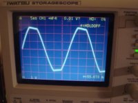
2.
Mostly the same but with less gain in the inner loop (more rugged vs. disturbances for the breadboard design....) an additional OP amp and nested feedback structure. Well and with a stronger supply... The additional OP enables symmetric input, higher input impedance, higher closed loop gain and at the same time higher feedback.
Feedback structure is nested.
Overall we may simplify (well, for details we may not.... feel free to simulate..) it to a feedback somewhere around 60db at 1kHz, but with mostly integrating behavior over the audio band.
Clocked design.
Clipping behavior is showing a medium level of "stickyness", but still not catastrophic to my ears. The shown screen shot shows clipping at 500W into 2R.
Related Schematic: schem_highfeedback.pdf
Related clipping screen shot: clip_highfeedback.jpg , (10:1 probe)
I think there is no doubt that good clipping behavior is no big deal at feedback levels around 20db-30db also for post filter feedbacks.
The entire discussion is not worth much with out the following informations.
-Feedback structure: Post filter, pre filter, mixed.
-Feedback characteristic: PID etc.. , or even better a simplified drawing.
-Amount of feedback depending on frequency.
-Clipping method: Natural clipping, pre clipper, non linear feedback, reducing forward gain at higher output levels
, ....?....-Clocked / self resonant
I will make the start with two of my oldies:
My current design approaches are simply not ready yet and still just
on the level of simulations.... so I hope you are not bored by my old stuff.
It is just an example of how I would love to see you turning your comments into a technical discussion.
1. A low feedback solution, providing approx. 30db feedback over the entire audio range. Well 30db in the shown load case (clipping into 2R5), which makes the weak supply sagging from +/-55V down to approx. +/-30V...
Clocked design.
Feedback structure is mixed pre & post filter feedback.
Already the natural clipping behaviour is absolutely blameless.
Related Schematic: schem_lowfeedback.pdf
Related clipping screen shot: clip_lowfeedback.jpg , (10:1 probe)
2.
Mostly the same but with less gain in the inner loop (more rugged vs. disturbances for the breadboard design....) an additional OP amp and nested feedback structure. Well and with a stronger supply... The additional OP enables symmetric input, higher input impedance, higher closed loop gain and at the same time higher feedback.
Feedback structure is nested.
Overall we may simplify (well, for details we may not.... feel free to simulate..) it to a feedback somewhere around 60db at 1kHz, but with mostly integrating behavior over the audio band.
Clocked design.
Clipping behavior is showing a medium level of "stickyness", but still not catastrophic to my ears. The shown screen shot shows clipping at 500W into 2R.
Related Schematic: schem_highfeedback.pdf
Related clipping screen shot: clip_highfeedback.jpg , (10:1 probe)
Attachments
...obviously the results are considered according to the specific of project.(if high fidelity or commercial audio)
?...do you want to say...?
HiFi: Clipping unimportant, because in HiFi we don't go into clipping...
PA, commercial: Clipping must not cause interuptive sounding effects and failures ..
Furtheron, in the original question there was also the topic of oscillations and rectangular 10khz signals up the clipping limit.
Do we need perfect 10khz rectangulars up to clipping limitations?
Another thing which I saw in the measurements of abletronics:
They are always talking about oscillations....
But referring to their screen shots we would obviously have to split these so called 'oscillations' into different topics.
- Carrierer aliasing
- Instabilities triggered by large step responses
- Instabilities at high load impedances
- Overshoot ringing due to underdamped closed loop response
- Overshoot ringing at large signals due to the fact the switches in front of the filter cannot deliver voltages beyond their rails, but for blameless rectangular shapes behind the filter you have to feed the filter with voltages which are much higher than the output voltage....
Hi,
I mean "natural clip" because I can get many important info on it.
Sure, you can force limiter pre-clip for clean (loss efficiency), on commercial audio and high power ,this is possible and help reliability.
In High fidelity is important show natural clip as clean possible because use this area near vcc.(dynamics is not controllable).
Then, to get a clean clip is not easy, this depends on many factors.
hysteresis, NFB, delay, phase shift (input / output), Deadtime (time and phase).
and last .. modulator (if clocked yet other factors). trw linearity and geometry.
this if I want perfect class D amp. or supplies with +/-80V and limit at 60vP out.
Regards
Last edited:
Hi,
I know I was not .. Loved . but this is not important.
ChocoHolic,What is delay (input to output pre-filter) in your applications ? (at carrier frequency).
Makes no sense to develop complex feedback, why I can not put a simple resistors on output to input ? (as Class A-B feedback). There is a reason. So this is what I have to solve. Solution ...go to a new concept di class D.
Regards
...if I remember right, from comparator input to MosFet output approx. 300ns. No trouble, at such lowish feedback levels.Hi,
...
ChocoHolic,What is delay (input to output pre-filter) in your applications ? (at carrier frequency).
Obviously the reason for different feedback requirements of class D vs. class A-B is the traditional 2nd order LC output filter, which gives us a 180 degrees phase shift (delay) above its resonance frequency. And the lovely filter resonance, which asks for being dampened (passively or actively)..... why I can not put a simple resistors on output to input ? (as Class A-B feedback). There is a reason. So this is what I have to solve. Solution ...go to a new concept di class D.
A common solution (and IMHO not bad) for post filter feedback of clocked designs is to settle a PID structure.
Simply show us how your di class D is working.
- Status
- This old topic is closed. If you want to reopen this topic, contact a moderator using the "Report Post" button.
- Home
- Amplifiers
- Class D
- English class D pro audio amp