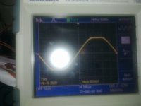
please can some one explain the wave forms of the test results on this amplifier,think they are poor and are they typical of class D
HTTP://www.abeltronics.co.uk/amptesting.php?z=funktion-one_f60Q_-_ffa6004

look under amp testing
HTTP://www.abeltronics.co.uk/amptesting.php?z=funktion-one_f60Q_-_ffa6004
look under amp testing
Last edited:
Hi Andy,
If you have been looking at this then I am sure that you have also seen the other tests by Abeltronics? He has tested various Class D-amplifiers and only a few have shown these sorts of severe results on a scope. Namely Powers oft and PKN.
I myself run large Lab Gruppen Class D (ish) amps that exhibit none of this.
I myself have also tested the amps in question in blind ab tests (well the 4004 version from FFA) and was not happy with the sound quality. We found its sound to be hard and abrasive above about 3-4k.
There are most definately good and bad ways to design all topologies
Kindest Regards
I have tested the labs,they are class G were the booster(tracking supplies are pwm based buck converters) are tracking unlike the switched class H.
I like the labs But i am shocked by the utter lack of consideration as too the quality of this amplifier on the albertronics sight.
I used to design Hi-Fi amplifiers many moons ago.
and these days some manufacturers just produce utter Junk.
I think the customer will lose out,maybe the PA industry needs to be well cleaned up.
I was wondering if you would pick up on the Lab Gruppen topology comment.
I thought that that must have been you Andy!
I told you that these amps were hard and abrasive and really do not compare with the PKN and Powersoft current class D designs.
In case you hadn't realized, Tim From Secrets Of Sound Here.
Hows development going?
Hadn't heard from you or Matt in a while?
How are you by the way?
A poorly implemented Class-D by those "Engineers" who think designing a switching amplifier is same as linear amp.
The result is obviously as crappy as one could expect.
Whereas,
When things are neatly engineered, the results[My 5KW CLass-D] are somewhat Cool
The result is obviously as crappy as one could expect.
Whereas,
When things are neatly engineered, the results[My 5KW CLass-D] are somewhat Cool
Attachments
Last edited:
A poorly implemented Class-D by those "Engineers" who think designing a switching amplifier is same as linear amp.
The result is obviously as crappy as one could expect.
Whereas,
When things are neatly engineered, the results[My 5KW CLass-D] are somewhat Cool
Robust results Workhorse.
Keep the good work
neighbours envy , owner's pride
Evita, its not "Preclipped" at input or anywhere else , i use another technique to get STICK FREE CLIPPING
The output signal shown by Workhorse is pre-clipped, it's a valid method to obtain clean clipping, but it does not reveal actual amplifier behaviour.
Evita, its not "Preclipped" at input or anywhere else , i use another technique to get STICK FREE CLIPPING
Last edited:
Whereas,
When things are neatly engineered, the results[My 5KW CLass-D] are somewhat Cool
Hi,
would you be able to achieve the same results in clocked design with 25-30 dB of loop gain at 10kHz?
Hi,
would you be able to achieve the same results in clocked design with 25-30 dB of loop gain at 10kHz?
Yes, but in my clocked modulator the magnitude of loop gain is somewhat different at 10khz.
Last edited:
A poorly implemented Class-D by those "Engineers" who think designing a switching amplifier is same as linear amp.
The result is obviously as crappy as one could expect.
Whereas,
When things are neatly engineered, the results[My 5KW CLass-D] are somewhat Cool
Hello Workhorse,
Care to share some photos of the beast?
It's very rare these days to see a KW level amplifier made by a diy enthusiast.
Kind regards,
Savu Silviu
Evita, its not "Preclipped" at input or anywhere else , i use another technique to get STICK FREE CLIPPING
The usual method is clipping error amplifier (integrator) output to 5% and 95% duty cycle, as seen from the input of the comparator. In fact, sticking is prevented more or less in the same way in self oscillating circuits.
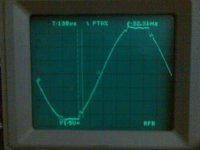
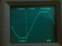
These images show 1khz clipping on a class-D full-range prototype employing my self-oscillating concept. Scale is 50V/div (10:1 probe). First picture is taken with no load at all and limiter disabled. Second picture is taken with 2 ohm load and limiter disabled too (150V peak into 2 ohms result in 11 kilowatts peak power
).Note how the control loop damps output filter ringing almost immediately when the unloaded amplifier recovers from clipping, in other words, loop transient response is good. The artifacts on the waveform are all above 20khz. Sticking only lasts 20 microseconds. It could be further improved, but circuit complexity would increase quickly, and once the limiter is enabled only very brief clipping is allowed, so it's not worth the effort.
BTW: No RC zobel is used at the output.
Brands like FFA or PKN should be ashamed of releasing such poor products to the market. They offer nice websites full of marketing literature, fashion rack cases, and not much more
Attachments
Last edited:
The usual method is clipping error amplifier (integrator) output to 5% and 95% duty cycle, as seen from the input of the comparator. In fact, sticking is prevented more or less in the same way in self oscillating circuits.
Thats what you thought i might be doing, but it wasn't, the trick is in the feedback loop itself which gives me STICK FREE CLIPPING
These images show 1khz clipping on a class-D full-range prototype employing my self-oscillating concept. Scale is 50V/div (10:1 probe). First picture is taken with no load at all and limiter disabled. Second picture is taken with 2 ohm load and limiter disabled too (150V peak into 2 ohms result in 11 kilowatts peak power
Note how the control loop damps output filter ringing almost immediately when the unloaded amplifier recovers from clipping. The artifacts on the waveform are well above 20khz.
Once limiter is enabled, only very brief clipping is allowed.
With your sooo much effort , Sticking is still Visible there in your waveforms
look at new version of UCDs their clipping also appear cleaner than your waveforms.
BTW: No RC zobel is used at the output.
RC zobel should be used when you want to FRY the zobel resistor with smoke only
.Brands like FFA or PKN should be ashamed of releasing such poor products to the market. They offer nice websites full of marketing literature, fashion rack cases, and not much more
They are already ashamed after looking at my stick free waveforms for class-D, remember this forum is full of spies
Last edited:
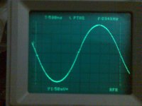
Carrier residual at the output, at 500mV/div. No parasitic RF
Self-oscillating circuits require a high quality carrier residual anyway.
My "sooo much effort" for preventing sticking at clipping only turned into two transistors and four resistors in this prototype. There is not much room in the PCB
Self-oscillating circuits require a high quality carrier residual anyway.
My "sooo much effort" for preventing sticking at clipping only turned into two transistors and four resistors in this prototype. There is not much room in the PCB
Attachments
Last edited:
Nothing New..........
C'mon Evita,
Having carrier residual free of RF ringing is easily achievable, See the UCD for example, If one pays attention to layout of pcb and placement of components along with optimum deadtime setting[one diyer named Bender already demonstrated it in another thread]
See this, people have already done it. Nothing neW
http://www.diyaudio.com/forums/class-d/116590-ucd-like-topology-amp.html#post1416458
and making a 11kw peak only power amplifier with clip Stick waveforms just because you dont have PLACE for 2 trannys and 4 resistors is quite>>
Cheers!!!
Carrier residual at the output, at 500mV/div. No parasitic RF
Self-oscillating circuits require a high quality carrier residual anyway.
My "sooo much effort" for preventing sticking at clipping only turned into two transistors and four resistors in this prototype. There is not much room in the PCB
C'mon Evita,
Having carrier residual free of RF ringing is easily achievable, See the UCD for example, If one pays attention to layout of pcb and placement of components along with optimum deadtime setting[one diyer named Bender already demonstrated it in another thread]
See this, people have already done it. Nothing neW
http://www.diyaudio.com/forums/class-d/116590-ucd-like-topology-amp.html#post1416458
and making a 11kw peak only power amplifier with clip Stick waveforms just because you dont have PLACE for 2 trannys and 4 resistors is quite>>
Cheers!!!
Last edited:
They are already ashamed after looking at my stick free waveforms for class-D
Before someone will be ashamed, it is needed to know first, how deep is your loop gain at various frequencies, and whether you use an integrator at all... It is very easy to get "stick free clipping" with small loop gain, I would say
(or without any feedback at all )But if you really use some high order modulator with such advanced clipping behaviour, then indeed it is a good job...
- Status
- This old topic is closed. If you want to reopen this topic, contact a moderator using the "Report Post" button.
- Home
- Amplifiers
- Class D
- English class D pro audio amp