Hi,
certainly agree with current diagram can not be put in simple feedback resistor.
I maintain that now you can get a result equal to an amplifier esoteric, employing only the modulator with a triangle wave. (not selfoscillator). this is my experience.
But even this is not easy. requires much knowledge of details that normally escape.
Soon I decided to released an amp complete of gerber for DIY free.
ok...not only for DIY
Based on high resolution 400KHz modulator. this amplifier has very high performances up to 30KHz (not at 10KHz increment thd) and not increment thd vs. power up to 94% of modulation. we can talk after commenting on the various solutions adopted (with pleasure).
Regards
Hi,
ChocoHolic,What is delay (input to output pre-filter) in your applications ?
Have to correct myself. It was not around 300ns. This old mostly discrete circuit was much faster.
Comparator: 20ns
Level shifter: 40ns
MosFet driver: 30ns
di/dt regulation plateau: 50ns (depending on load... 10n-80ns)
Miller plateau: 20ns
ugs-sloping: 10ns
I am going to try an analog switch in feedback path, which turns a global prop-integrator feedback into low feedback proportional whenever internal overload (slew overload, clipping, overcurrent etc.) is detected.
Hi Dark,
I am looking forward to see your results! This method to avoid diodes/zeners is sounding promising.
May we see a schematic?
...thanks for sharing.
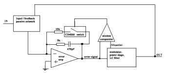
I am surprised that you feed the window comparator with the carrier.
How does this act in detail? If the difference between carrier and OP amp output exceeds a certain window, the you turn ON the switch? Or do you have sort of a dynamic window?
Without your scheme I would have thought to track only the output of the OP amp by a window comparator with a fixed window, - allowing everything between upper and lower peak of the triangle.
...would have been my straight forward thinking and would require to touch just one audio signal.
... curious about the reason, why you did different...
Without your scheme I would have thought to track only the output of the OP amp by a window comparator with a fixed window, - allowing everything between upper and lower peak of the triangle.
At high modulation index, peak voltage of the OP amp can exceed peak voltage of the carrier (without real clipping). Carrier residual is amplified by error amp too, and it produces such effect...
No doubt, yes. If you go for strong feedback, then the signal of the error Amp may already exceed the triangle peaks at moderate modulation levels.
Never the less the max values are not random, but systematical. They can be determined for every design. Means - you may increase the window size depending on your circuit, with fixed limits for the window.
Unfortunately the more feedback you give, the worse the clipping behavior and also the worse the behavior at large rectangular input signals will become.
Its a trade off between feedback, distortion, clipping behavior / large rectangulars and personal taste - where and how to put the limit.
Idea is good but now I see "carrier" then this is not selfoscillant.
I think a problem (triangle is fixed amplitude),then level of feedback can not greater than it. also hysteresis....
certainly it can running good without of feedback. (only for control clip)
This is my opinion.
Regards
I think a problem (triangle is fixed amplitude),then level of feedback can not greater than it. also hysteresis....
certainly it can running good without of feedback. (only for control clip)
This is my opinion.
Regards
Last edited:
I forgot to say:
In order to minimize carrier aliasing at high modulation levels, it is
sometimes reasonable, to act already at the levels around the triangle peak.
Please note - darkfenriz is not doing a hard limitation of the error amp, he just eliminates the integrating portion of the error amp.
In order to minimize carrier aliasing at high modulation levels, it is
sometimes reasonable, to act already at the levels around the triangle peak.
Please note - darkfenriz is not doing a hard limitation of the error amp, he just eliminates the integrating portion of the error amp.
Sorry,this is a very interesting discussion because I know almost all amplifiers
have a bad clip (not good integration,hysteresis,all delay and very poor modulator).
Well, I do not agree if the result is clean the area of clips or high-level modulation.
window comparator can act on feedback but in reference to what?
Only a perfect integration (if the rest is perfect) you can get excellent high modulation. I just put 3-4 Screenshots with high level modulation just to see when it is perfectly clean (depends on what)
Last edited:
Why is it a dogma to have the amplitude of the triangle fixed?I think a problem (triangle is fixed amplitude)
Regards
IMHO it should also be possible increase the amplitude of the triangle in case of large output signals in order to avoid carier aliasing.
Also it should be possible to increase the amplitude of the carrier in case of excessive signals from Error Amp in order to keep the system calm in case of large rectangular input signals.
?certainly it can running good without of feedback. (only for control clip)
...don't get what you mean with that...
?
Why is it a dogma to have the amplitude of the triangle fixed?
IMHO it should also be possible increase the amplitude of the triangle in case of large output signals in order to avoid carier aliasing.
Also it should be possible to increase the amplitude of the carrier in case of excessive signals from Error Amp in order to keep the system calm in case of large rectangular input signals.
?
...don't get what you mean with that...
?
yes, no problem to change the amplitude of the triangle.
it is okay to move only offset of triangle (if you have a lot of speed)
outside the feedback, I meant only anti clips (type alc)
Last edited:
... ah well, I would not fully agree.Only a perfect integration (if the rest is perfect) you can get excellent high modulation.
As far as I see, at modulation high levels a slow integrating gain the only gain which does not cause headache (Edit: But why should it be needed at high modulation levels?).
P gain and D gain cause HF at the output of the error amp and may cause carrier aliasing.
But a soon as you exceed 100% modulation the integrator causes headache and also at large rectangular input signals.
So we would need two things:
1. Disable/reduce the integrator when the error amp signal exceeds the levels, which fit 100% modulation.
2. Reduce forward gain (and may be adjust D portion) at higher output voltages.
Last edited:
for reference only (not to criticize your work)
Your screenshot shows many defects with clipped signal over integration. example is the Unbalanced PWM. despite approximately 100ns propagation (input to MOSFET) has a lot of hysteresis. So, in your opinion what is wrong in that circuit?
Your screenshot shows many defects with clipped signal over integration. example is the Unbalanced PWM. despite approximately 100ns propagation (input to MOSFET) has a lot of hysteresis. So, in your opinion what is wrong in that circuit?
I see that we understand now.
it is clear that the modulator can not turn free.
but I do not agree that the window comparator resolves the problem.
I agree that the circuit of darkfenriz is motivated more by the goal to calm down the system in case of large rectangular input signals.
Not sure if it is bringing perfection, but I think it should bring a reasonable improvement.
for reference only (not to criticize your work)
Your screenshot shows many defects with clipped signal over integration. example is the Unbalanced PWM. despite approximately 100ns propagation (input to MOSFET) has a lot of hysteresis. So, in your opinion what is wrong in that circuit?
You mean the low feedback example?
The 'defect' is simply the sagging of the supply rail.
The frequency in the shown low feedback example was very low.
Of course it would have been nicer to have both screen shots at 1kHz,
but I simply took the pics which I found in my old thread.
http://www.diyaudio.com/forums/class-d/101774-1kw-gen2-5.html
- Status
- This old topic is closed. If you want to reopen this topic, contact a moderator using the "Report Post" button.
- Home
- Amplifiers
- Class D
- English class D pro audio amp