I have made smps 1500 watt selfoscilision but I have confused about some thing different as usual when I reduce volt to 40+ - I have super and beauty sound and efficient and when I produce volt to 80 + - the sound and heating doesn't very good like +-40 can any body help my to understand how does it possible?
My smps have very good efficient and am per I think that is the reason. !!!
My smps have very good efficient and am per I think that is the reason. !!!
hi ,friends
can this circuit works with +-40 volts?
i made a -+40 volt power supply and decided to make a power amp .
yes its working
no problem
but
+-40v
40*.8=32v (safe maximum PWM 80% (85%))
32/1.414=22.6V (rms output voltage)
22*22/4 == 120W RMS @ 4ohms (output power V*V/R)
may be 100W with coduction+capacitor Vdrops losses
60W @ 8ohms
so this is not effective circuit for low voltages
try +-80V or +-100V !!!!!be careful!!!
Last edited:
yes its working
no problem
but
+-40v
40*.8=32v (safe maximum PWM 80% (85%))
32/1.414=22.6V (rms output voltage)
22*22/4 == 120W RMS @ 4ohms (output power V*V/R)
may be 100W with coduction+capacitor Vdrops losses
60W @ 8ohms
so this is not effective circuit for low voltages *
try +-80V or +-100V !!!!!be careful!!!
thanks,
but what a bout "apex d200 " circuit ?
at schematic that is +-75 volts,at the pcb it's +-55 volts!
now can i feed it with +-40 volts/500 watts switching power supply? how many watts that power is?
Stewin:
Why using IRFB4227 MOSFETs with 20mOhm Rdson, when you put 0,1 Ohm resistors in series with them.
The MOSFET driving network is also very ineffective. 47 OHm turn-on resitors can be good for <100kHz. Also BD243 and BD244 is way too slow. Layout is very poor. Some advices:
- Use a pair of very fast SOT-23 SMD transistor to boost gate drive (for example MMBT2222A and MMBT2907A is good) rigth next to the MOSFETS. Use a ceramic cap to filter the supply of these SMD BJTs. This will decrease the gate drive length extremely. So less inductance, faster driving, less noise.
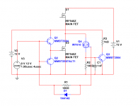
- Forget the shunt protecting, it will have more loss than all other parts of the amplifier! Use the FETs for shunt, previousle I posted a simple schematic that does this, here it is again:
View attachment 369447
As you can see MMBT2907A boosts the turn off, and MMBT3904 the turn off, the first one is smaller.
U1 and U2 are the main FETs. When U2 turns on, the gate signal turns on the Q4 auxiliary FET (the 100 ohm resistor is for this FET should turn on a bit later). The R2 and C1 filters the swithced half bridge signal for spikes. IF the votlage drop at U2 main FET is at least 0,6V (about 20-30A per IRFB4227) it turns on Q3. The output signal from its collector then can be fed to an 555 timer to turn on protection.
The aux FET should have a very small Qgate and Coss, Rdson does not matter.
- Snubber desing is also very bad. RC snubber should be as close to the FETs as possible (1 RC snubebr per FET), because in reality it is an RLC snubber, if L is too big, it will help nothing, it will only make thing worse.
Still lot to learn")
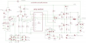
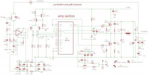
hi all does anyone know how to impliment this protection circuit . while using ir2110 and irfb4227 in ucd configuration Attachments
Last edited:

problem is (RDs on IRfb4227 = 20mili ohm) ocp current 35A
(RDS on irf540z= 77mohms)ocp current 9A
pls post protect schematic which will work with +/-85volts 1pair of irfb4227 with 2ohms load ir2110 .
the class d i like using is ucd
Nice thread.
I do read however that people has problems with hot fets and such.
As with all switching devices, the mosfets need to get fully closed and dead times is needed, (beware, just some nanoseconds because it will de audible when coil collaps).
I did read that for nice sound a analog driven class D is better, as compare with past these amps are a lot better then in the old times.
Use not old fets, to slow, there are better ones, faster, less capacity, do drive them with good driver who is capable to drive that capacity of gate, and fully so mosfet do close and opens completely, a lot of heat problems is because of this, it is like smps drive them properly.
regards
hi kees .do you have any nice working schema you share??
I have now some projects, but I am study now some class D amps, special analog pwm serie.
here are maybe some ideas, and if I have some more I will share, but it needs time for me to studie first and sim, as trynergy is ready.
I did read not much experienced designers for class D, I belong to them.
regards
Attachments
Last edited:
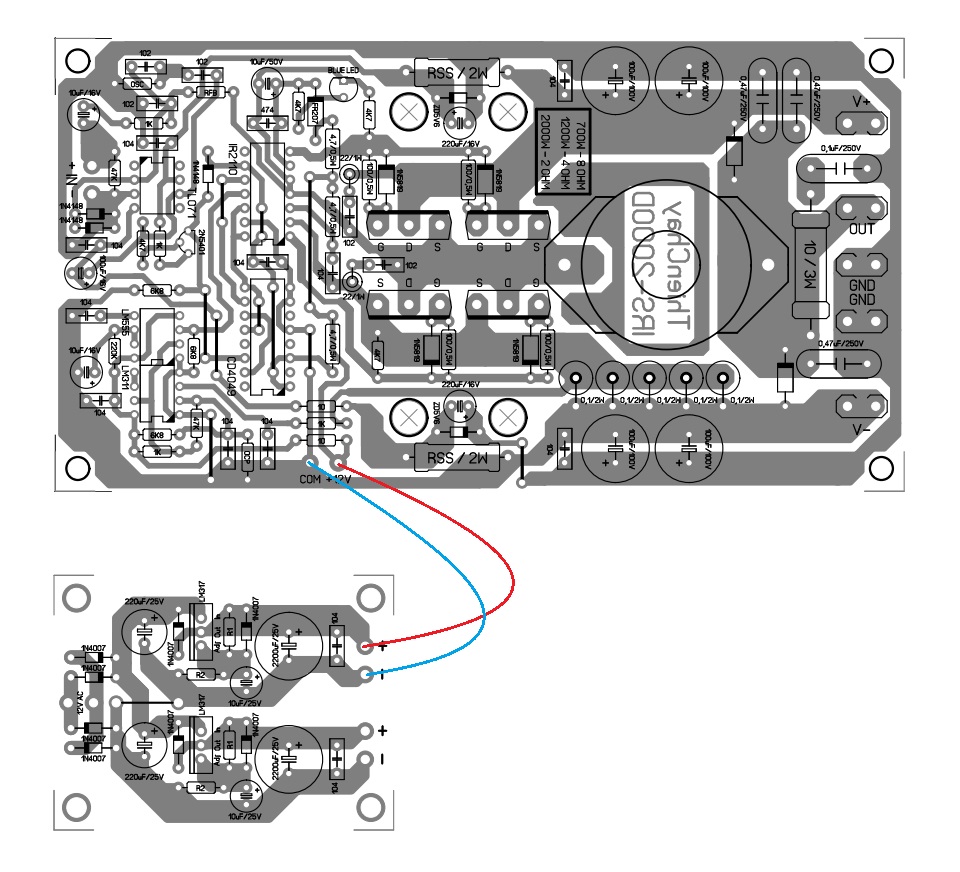
hi all by the grace of GOD i have finished a layout with ocp,dcp,ovp,uvp and soft start protections .the relays are small but i prefer using relays to reduce on pop and off discharging noise. i intend to use +/-85volts at 2ohms outputs are one pair irfb4227 .
if interested to make pls do and post photos and your experience.
have fun guyz
any ideas comments are welcomed
if interested to make pls do and post photos and your experience.
have fun guyz
any ideas comments are welcomed
Attachments
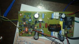
D2k neo
Pcb done and chake
But now offset is -7 vdc
This is my Schematics D2KNeo and PCB picture. Just to give you idea, of maybe redraw from this picture. 2 sets mosfet Class D. I cannot give PDF of layout. You cannot just simply move this picture as some tracks are optimized to get very less capacitance hence as small as possible for small signal. Just give you idea.
Regards,
kartino
Pcb done and chake
But now offset is -7 vdc
Attachments
problem is (RDs on IRfb4227 = 20mili ohm) ocp current 35A
(RDS on irf540z= 77mohms)ocp current 9A
It's not a problem. 20 mohm if it's cool. But no reason to shut down if cool. Protection is needed if MOSFET chip is hot, but then Rdson will be around 50 mOhm, so at 14 A it will shut down. This kind of protection is extremely effective if implemented well (correct timing, sensing for both polarity).
- Home
- Amplifiers
- Class D
- UCD 25 watts to 1200 watts using 2 mosfets