hi,
I understand that can be used to test, but you lose your time, work all signals incorrect up to driver .
In theory at Bridge 2 Amp (+ /-100V) produce 2500W @ 8R.
I do not think is appropriate for first Class D amplifier.")
Hi,
If to replace on D1 on ad817 then it will be much better, what else it is possible to improve in this circuit? By my approximate calculations in bridge inclusion should be 4000W@4R.
hi,
I have only applied the formula to the theory of 200vp out.
3 parameters are needed for accurate power Out
load, rail voltage (power supply voltage decrease under current), and Vp on load
(Rail voltage - inefficiency of power out stage)
this for continuos power. (peak power is higher, becouse probable use big capacitors on voltage) this is measured with adequate burst signal on amplifier.
your scheme is too simple to support a very fast op-amp or comparator.
new circuit must be designed, including pre-driver solutions must be good.
your scheme is too simple to support a very fast op-amp or comparator.
new circuit must be designed, including pre-driver solutions must be good.
For me the main priorities of the given class it is efficiency, power, quality, by such principle I shall aspire to develop the given circuit. The prototype is conceived not for reception of very high parameters and for the first experiment, one watt on 4 ohms would suffice also. That you particularly could recommend to change in my circuit and that you mean under pre-driver solutions. Why you count not justified application of faster op-amp or comparator?
I wanted to tell 1KW on 4 ohmsFor me the main priorities of the given class it is efficiency, power, quality, by such principle I shall aspire to develop the given circuit. The prototype is conceived not for reception of very high parameters and for the first experiment, one watt on 4 ohms would suffice also. That you particularly could recommend to change in my circuit and that you mean under pre-driver solutions. Why you count not justified application of faster op-amp or comparator?
Hi all
This amp will work indeed, because its a circuit layout of a "irf example class-d amp application note" thats almost identical to the orignal ! i shall post the real deal on monday!
i was looking at this circuit just lastnight noticed the input stage that smelled familiar :-D
This amp will work indeed, because its a circuit layout of a "irf example class-d amp application note" thats almost identical to the orignal ! i shall post the real deal on monday!
i was looking at this circuit just lastnight noticed the input stage that smelled familiar :-D
Last edited:
Question: whether If to do a bridge exit and a unipolar power supply that it will be necessary levelshifter stage?
it is better to use a bipolar power supply here
Otherwise you will need to have some reference voltage at the input integrator (TL081), you will get a big CLICK/POP at startup, maybe it will not start to oscillate at all, you will get the problems with non symmetrical clipping and so on...
CMOS can work great as a comparator
I chose the CD 4049 using 2 stages
before this the audio feeds into an LF353 (fantastic stability)
The output drives the low side MOSFET with an NPN PNP totem pole pair
The high side is also discrete
12v supply 15ns switching time (at first stage output)
My amp runs +- 42 Volts , 1.25 Mhz, 3 channels Left - Sub - Right
The topology is DC coupled except for signal input capacitor
Audio gain 25 db Dc offset 2.5 Millivolts
I have yet to do a distortion test, but there are no audible artifacts
Hi,
maybe it's better that you have not measured IMD, THD and efficiency.
LF353 has a linear behavior (used as a comparator) up to 150 kHz.
this low frequency and slow switching time are not adequate for medium-good result of audio.
I'm curious to see the signal at the gate mosfet your amplifier at 1.2 Mhz.
totem-pole(NPN-PNP) for drive mosfet is good.
is possible see partial of you scheme?
If you want, I can illustrate with waveform, why not very good LF353.
----------------------------------------------------Hi,
maybe it's better that you have not measured IMD, THD and efficiency.
LF353 has a linear behavior (used as a comparator) up to 150 kHz.
this low frequency and slow switching time are not adequate for medium-good result of audio.
I'm curious to see the signal at the gate mosfet your amplifier at 1.2 Mhz.
totem-pole(NPN-PNP) for drive mosfet is good.
is possible see partial of you scheme?
If you want, I can illustrate with waveform, why not very good LF353.
I'm sorry, I have not read the first part of your post.
Moon are... sometimes.
then very interesting your project.(if you put a primary FB post LF353)
Last edited:
The oscillation is controlled by the HEF4049 (4050 can be used as well)
and the Mosfet output stage. The 2n4401 feeds a 27ohm resistor to the gate
A 2N5401 sinks the gate current through a 3.3 ohm resistor.
This provides proper dead time in the Turn on phase of operation
there is about 500mv of Near sinusoidal output voltage on the 353 feeding a
level shifting 2N5401. I still need to design an over-current shutdown circuit
I am thinking of selling a board for this amp.
The amplifier is work! But there is a problem: at inclusion sometimes there is a constant pressure (already 3 dynamics has burnt), and at deenergizing of races of 2 volts. What can it be and how to cure, it would be desirable to make stable smooth start and amplifier deenergizing, whether there was at you a similar problem? Output mosfets - irfp260, the driver ir2110.
Hi Vogor
Is it the same schematic as in post #1????
What supply voltage are you running?
Not, sure I understand; at start up the amplifier is butning your speakers??
Are you sure it actually starts up (oscillate) every time?? Or does the output just swing to one of the rails (high DC)
(Yes I have had a lot of trouble not getting the amp tor start oscillating ...... not totally sure how tohelp this in your design though ... will think it over)
Do you use any fuses in the rails? (I use polyfuses for prototyping ... as I wrote some messages ago)
Use a dummy load of 8 ohm, until you are sure it starts up properly.
Is it the same schematic as in post #1????
What supply voltage are you running?
Not, sure I understand; at start up the amplifier is butning your speakers??
Are you sure it actually starts up (oscillate) every time?? Or does the output just swing to one of the rails (high DC)
(Yes I have had a lot of trouble not getting the amp tor start oscillating
...... not totally sure how tohelp this in your design though ... will think it over)Do you use any fuses in the rails? (I use polyfuses for prototyping ... as I wrote some messages ago)
Use a dummy load of 8 ohm, until you are sure it starts up properly.
Yes, scheme that I have resulted in the thread beginning, a power supply voltage +/- 65VHi Vogor
Is it the same schematic as in post #1????
What supply voltage are you running?
Not, sure I understand; at start up the amplifier is butning your speakers??
Are you sure it actually starts up (oscillate) every time?? Or does the output just swing to one of the rails (high DC)
(Yes I have had a lot of trouble not getting the amp tor start oscillating
Do you use any fuses in the rails? (I use polyfuses for prototyping ... as I wrote some messages ago)
Hi!
Use a dummy load of 8 ohm, until you are sure it starts up properly.
I have really burnt three dynamics from for constant voltage which appears and then at repeated inclusion it is not present also the amplifier normally works, I think that a problem in transient at start but I do not know as it to eliminate. Fuse did not use.
Yes, scheme that I have resulted in the thread beginning, a power supply voltage +/- 65V
I have really burnt three dynamics from for constant voltage which appears and then at repeated inclusion it is not present also the amplifier normally works, I think that a problem in transient at start but I do not know as it to eliminate. Fuse did not use.
+/-65V without fuses - you are crazy!
Use it at least at the output! Did you followed your schematics precisely or you have skipped some parts from it?
Please post the photos of your prototype here (both pcb sides) and I can try to give some recommendations for you then I think it is almost impossible to remove the POP at startup in this schematic. Look at the startup circuit on T2, this is intended to generate a long negative output impulse at startup, to charge the driver bootstrap cap and to initiate the oscillation. In original IRAUDAMP1 they have used an output relay, which was intended to block this POP from speaker.
Also, I recommend to use some emitter followers to generate +/-5V voltage for input stage, because R11 and R12 with 4.7K can produce too low current to power up the input stage (at +/-65V this gives only 12mA).
Last edited:
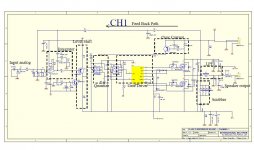
This is the original circuit from IR, i dont know where the author got hes design from no wonder NO "design" or implmentation detail is given(typical when you copy and paste other peoples work.)
see below for the orignal design, the one posted here has some addtional changes supply changes and active component changes ect.. without reason behind it.
http://www.irf.com/product-info/audio/classdtutorial.pdf
note the orignal doesnt give design detail just high level notes on how to go about designing a class d amp usefull for "us" newbies
Attachments
Last edited:
- Status
- This old topic is closed. If you want to reopen this topic, contact a moderator using the "Report Post" button.
- Home
- Amplifiers
- Class D
- Self-oscillating class D amplifier