Yes, scheme that I have resulted in the thread beginning, a power supply voltage +/- 65V
I have really burnt three dynamics from for constant voltage which appears and then at repeated inclusion it is not present also the amplifier normally works, I think that a problem in transient at start but I do not know as it to eliminate. Fuse did not use.
Here is how I recommend to change your power circuit for input stage (see image attached). Sure, it needs to be done for both +5V and -5V sides...
Attachments
HI,
is likely to get less "PUP" if disconnected collector of "CUT-OFF" BJT.
this is very old scheme. (IR did not know what he was doing)")
Without this 'cut-off' BJT this shematic may not start to oscillate at all, because the bootstrap cap of high-side driver is not charged yet at startup and it is why it needed to initiate the oscillation with negative POP pulse...
Last edited:
Photo I can to add later, but on a PCB there exist a ground contour. For tests except speakers I also used the self-made resistor 4ohm/50W, the problem in that that constant voltage on an exit appears any way (similar while bootstrap the condenser will not be charged). I followed the scheme completely only have changed a range supply voltage of the entrance operational amplifier on +/-15V, R11, R12 - 1,8K/2W. In the original scheme of the relay it is used for elimination of this "PUP", what is possible made for its elimination to make soft start without any undesirable effects? There is an idea for scheme start to connect Vb the driver to + hi mosfet and remove Т2 making impulse. Has not understood for what you have suggested to add the transistor on + a conductor.
To 81bas.
ok, except that in the schematic (IR) position of H-in/l-in is inverted (I looked up).
but the cut-off is still very, operational at this strength to positive output. (becouse FB)
very small low-side conduction is necessary for oscillation.
After not good solution is: curent sensing one side.very small boot-strap CAPC (0.33 uF) and redundant first stage (with inverter).
you are very careful on schematics...this is very good
Photo I can to add later, but on a PCB there exist a ground contour. For tests except speakers I also used the self-made resistor 4ohm/50W, the problem in that that constant voltage on an exit appears any way (similar while bootstrap the condenser will not be charged). I followed the scheme completely only have changed a range supply voltage of the entrance operational amplifier on +/-15V, R11, R12 - 1,8K/2W. In the original scheme of the relay it is used for elimination of this "PUP", what is possible made for its elimination to make soft start without any undesirable effects? There is an idea for scheme start to connect Vb the driver to + hi mosfet and remove Т2 making impulse. Has not understood for what you have suggested to add the transistor on + a conductor.
Why was you needed to increase the supply voltage for opamp to +/-15V ? Most of them are working fine with +/-5V also... And altering the supply voltage of opamp you need to alter the resistance of R9 too! So I recommend simply change it to +/-5V back...
Connecting Vb of the driver to +65V will kill your driver immediately! You can only tie it to +65V via a small resistor (about 50-80K) and connect the 15V Zener diode parallel to C13.
The 'transistor on + conductor' will give you more stable voltage for the input stage. The same needs to be done on '- conductor' too.
I increase the supply voltage for opamp to +/-15V because have assumed that its speed thus will increase, what value of resistance R9 in this case is necessary?
Vb to +65 I planned to connect through the resistor 100-200к, whether it is possible to expect normal start without an output impulse (If to remove T2)?
The ' transistor on + conductor ' will increase stabilisation factor? It is possible to see a variant for a minus conductor?
How you estimate at a supply voltage +/-100V the amplifier will give out 1000W? I also asked earlier about a bridge exit in the given scheme and a unipolar voltage source, it is possible, whether will be necessary in this case levelshifter (T1)?
PS Many thanks for explanations.
I increase the supply voltage for opamp to +/-15V because have assumed that its speed thus will increase, what value of resistance R9 in this case is necessary?
It is not necessary to have a high speed opamp at the input in this selfoscillating amp... So simply replace Zener diodes with another 5.1V
Vb to +65 I planned to connect through the resistor 100-200к, whether it is possible to expect normal start without an output impulse (If to remove T2)?
I think it will work...
The ' transistor on + conductor ' will increase stabilisation factor? It is possible to see a variant for a minus conductor?
For a minus conductor it will be the same, but the transistor should be of other polarity (NPN/PNP)
How you estimate at a supply voltage +/-100V the amplifier will give out 1000W?
With IRFP260 you used, this amp will die at +/-100V with 1000W at output...
I also asked earlier about a bridge exit in the given scheme and a unipolar voltage source, it is possible, whether will be necessary in this case levelshifter (T1)?
PS Many thanks for explanations.
You can bridge two of these amps without any problems. But it is too hard to rebuild this amp for unipolar voltage source...
amp
hello,can i have a full complete schematic of this amp please....here is my email adress ionutzxpo@yahoo.com thank you! ill give it a try
hello,can i have a full complete schematic of this amp please....here is my email adress ionutzxpo@yahoo.com thank you! ill give it a try
It is not necessary to have a high speed opamp at the input in this selfoscillating amp... So simply replace Zener diodes with another 5.1V
I think it will work...
For a minus conductor it will be the same, but the transistor should be of other polarity (NPN/PNP)
With IRFP260 you used, this amp will die at +/-100V with 1000W at output...
You can bridge two of these amps without any problems. But it is too hard to rebuild this amp for unipolar voltage source...
The amplifier works and starts now normally! but at deenergizing there was a small impulse (2V) that it and how it is possible to correct it, can switch off at first the driver and then other power supply? At a +/-100V I am going to use on exit IRFP4227 (on Vds and a Id approach) with them as think it will give out 1000W or there is other reason limiting capacity? What on yours difficult in transfer of the scheme into the bridge? I plan to add one more driver and pair mosfets, but whether will be still necessary levelshifter if to make unipolar power supply?
The amplifier works and starts now normally!
Which changes you have done then?
but at deenergizing there was a small impulse (2V) that it and how it is possible to correct it, can switch off at first the driver and then other power supply?
Do you get this impulse immediately after switching amp off, or after some delay (3-5 seconds)? If you do not connect anything to the amps input, is this impulse (2V) still there after switching amp off?
At a +/-100V I am going to use on exit IRFP4227 (on Vds and a Id approach) with them as think it will give out 1000W or there is other reason limiting capacity?
With IRFP4227 this will work longer
What on yours difficult in transfer of the scheme into the bridge? I plan to add one more driver and pair mosfets, ...
The difficulty to change this amp to be a bridge amp is to change the feedback path. You need to include the second driver and pair of mosfets into feedback path also, otherwise they will stay not corrected and will produce some distortions...
Simply build one more amp with the same schematic and use them in bridge configuration!
but whether will be still necessary levelshifter if to make unipolar power supply?
Look at the shematic. The input opamp is referenced by the GND now. If you will use unipolar PSU, then GND will be the same wire as -V source, right? So input opamp will be referenced by -V source then and the amp at idle will geve you -V at output (-65V). So it is needed to create some custom reference voltage for opamp, change the feedback path. Who knows, how it will work then...
Has not understood that you has in view of: "re-write FB entrypoint. (pre-filter is vcc/2 potenzial)", it is possible more in detail or to see an example. "PUP" on amplifier it is eliminated.HI,
for unipolar supply, can remove levelshifter becouse com now is gnd,but this required a re-write FB entrypoint. ( pre-filter is vcc/2 potenzial).
this is critical modify.
have solved "PUP" on amplifier?
Has left a PSU +/-15V for opamp (at decrease to 5,1 V on an amplifier exit appears 3V and it is not removed), has removed T2 and has connected Vb to +65V through 200K.Which changes you have done then?
The impulse appears right after deenergizings and duration - is accompanied 1 second by a quiet sound. The amplifier connected to a source of a signal and without connection made an identical impulse.Do you get this impulse immediately after switching amp off, or after some delay (3-5 seconds)? If you do not connect anything to the amps input, is this impulse (2V) still there after switching amp off
The second feedback can be connected to other input opamp because of what there can be distortions? I already thought of inclusion of two amplifiers by the bridge, capacity should grow in 4 times(3200W if single 800W)?The difficulty to change this amp to be a bridge amp is to change the feedback path. You need to include the second driver and pair of mosfets into feedback path also, otherwise they will stay not corrected and will produce some distortions...
Simply build one more amp with the same schematic and use them in bridge configuration!
It is possible to specify that such "custom reference voltage for opamp"? The scheme it is possible to try simulate in microcap for example.Look at the shematic. The input opamp is referenced by the GND now. If you will use unipolar PSU, then GND will be the same wire as -V source, right? So input opamp will be referenced by -V source then and the amp at idle will geve you -V at output (-65V). So it is needed to create some custom reference voltage for opamp, change the feedback path. Who knows, how it will work then...
Last edited:
Has left a PSU +/-15V for opamp (at decrease to 5,1 V on an amplifier exit appears 3V and it is not removed), has removed T2 and has connected Vb to +65V through 200K.
Congratulations! well done!
I do not understand, why there can appear 3V at amp output appear, but it makes no sense anymore, since you solved the problems with POP and startup
The impulse appears right after deenergizings and duration - is accompanied 1 second by a quiet sound. The amplifier connected to a source of a signal and without connection made an identical impulse.
I think it is needed to generate the shutdown signal for IR2110 driver. For example, if the -V source is less than 15-20 Volts, then generate shutdown. If you need an example circuit for it, I try to paint
The second feedback can be connected to other input opamp because of what there can be distortions? I already thought of inclusion of two amplifiers by the bridge, capacity should grow in 4 times(3200W if single 800W)?
Well, if you want to experiment with it, just do it!
Theoretically it will work, but practically there are usually a lot of issues... It is possible to specify that such "custom reference voltage for opamp"? The scheme it is possible to try simulate in microcap for example.
I suggest, that you try to paint the schematic for unipolar amp yourself first, and I will try to find errors then
Originally Posted by vogor
Has left a PSU +/-15V for opamp (at decrease to 5,1 V on an amplifier exit appears 3V and it is not removed), has removed T2 and has connected Vb to +65V through 200K.
-------------------------------------------------------------
Hi Vogor,
is possible see last revision of you schematics?( for this problem and for redesign new ritch FB. (for unipolar supply))
regards
Hi,
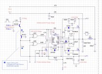
This is the output stage of my old project (2003).
component values are adjusted to obtain a good reproduction even at low audio frequency (40Hz) at power, and less noise as possible.
also the resolution at high frequencies sound is excellent.
nothing special, with this driver (IR2110 I used). I think they are all similar.
Regards
Attachments
Hi,
This is the output stage of my old project (2003).
component values are adjusted to obtain a good reproduction even at low audio frequency (40Hz) at power, and less noise as possible.
also the resolution at high frequencies sound is excellent.
nothing special, with this driver (IR2110 I used). I think they are all similar.
Regards
But this is NOT for unipolar voltage source? At least I see GND, -v and +V here...
- Status
- This old topic is closed. If you want to reopen this topic, contact a moderator using the "Report Post" button.
- Home
- Amplifiers
- Class D
- Self-oscillating class D amplifier