osscar-
That is actually pretty neat, certainly not safe, but neat.
It gives me some ideas for REALLY cheap builds for friends. I usually make and give away several chip amps but the cost of the enclosure is generally the limiting factor. This opens all sorts of possibilities.. And the recipients would probably think it's cool to "see" the parts. Of course I have to make it idiot proof. Even though they are making better idiots every year...")
That is actually pretty neat, certainly not safe, but neat.
It gives me some ideas for REALLY cheap builds for friends. I usually make and give away several chip amps but the cost of the enclosure is generally the limiting factor. This opens all sorts of possibilities.. And the recipients would probably think it's cool to "see" the parts. Of course I have to make it idiot proof. Even though they are making better idiots every year...
тпп 287-220-50К Old soviet transformer with primary 220V and six secondaries -
2x2,63V 2x5V 2x10 V - actual readings 2x16VAC in series.
90VA total.
There is also version where whole transformer was immersed in green paint .
This transformer is very quit - no buzz or hum like from cheap toroid.
2x2,63V 2x5V 2x10 V - actual readings 2x16VAC in series.
90VA total.
There is also version where whole transformer was immersed in green paint .
This transformer is very quit - no buzz or hum like from cheap toroid.
Hi to ALL!
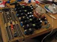
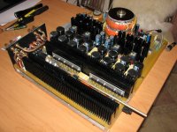
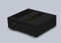
It is my new project of the 20W/4 Ohm or 10W/8 Ohm Class "A" amplifier on integrated microcircuits with 41 pieces BUF634T in each channel, included in parallel.
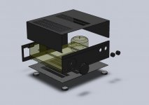
The amplifier works some months, but cases while is not present. Now the case is made at factory under my drawings. I wait for the termination of works.
Sounding was pleasant to all who came to me and listened
Photo of the amplifier I apply.
Other files:
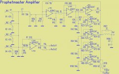
- Circuit of Amp
- Computer model of case
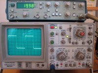
- Impulse signal 1 kHz
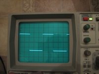
- Impulse signal 10 kHz
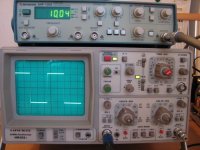
- Impulse signal 20 kHz
- Sin 5 Mhz
It is my new project of the 20W/4 Ohm or 10W/8 Ohm Class "A" amplifier on integrated microcircuits with 41 pieces BUF634T in each channel, included in parallel.
The amplifier works some months, but cases while is not present. Now the case is made at factory under my drawings. I wait for the termination of works.
Sounding was pleasant to all who came to me and listened
Photo of the amplifier I apply
.Other files:
- Circuit of Amp
- Computer model of case
- Impulse signal 1 kHz
- Impulse signal 10 kHz
- Impulse signal 20 kHz
- Sin 5 Mhz
Attachments
-
 Without cooling radiators1.jpg98.9 KB · Views: 2,504
 -
 Condition for today1.jpg96.8 KB · Views: 2,455
 -
 Circuitry.JPG119.1 KB · Views: 2,408
 -
 Case assembly drawing.jpg63.9 KB · Views: 2,340
 -
 General.jpg43.7 KB · Views: 2,258
 -
 Impulse 20 kHz1.jpg80.4 KB · Views: 355
 -
 Impulse 10 kHz1.jpg78 KB · Views: 334
 -
 Impulse 1kHz1.jpg55.9 KB · Views: 656
 -
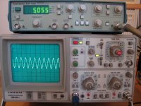 Sin 5 MHz1.jpg79.1 KB · Views: 362
Thanks!Original idea. Should R108 not connect to the other side of R107?
Can be and so, but I consider that this R-C should be from outside a loudspeaker.
Thanks for an appreciation.What an art of engineering Prophetmaster! You even manage to put resistors between heatsink's fins
Radiators are lifted over the circuit board on 5 mm and resistors are under cooling radiators
JFet Buffered Gain Clone. This is my first GC.
An externally hosted image should be here but it was not working when we last tested it.
An externally hosted image should be here but it was not working when we last tested it.
An externally hosted image should be here but it was not working when we last tested it.
An externally hosted image should be here but it was not working when we last tested it.
An externally hosted image should be here but it was not working when we last tested it.
MY FIRST PROJECT (almost Fisher Price!)
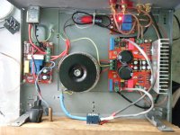
Budget MK1 special Lm3886 Juanjing amp board.
Upgrades include higher value input caps and resistors.Some resistors changed to carbon comp type.These mods suggested by linuxguru on "amazing ebay value" thread.
Transformer (to be upgraded ) and heatsink from defunct midi system.
Soft start and speaker relay boards.
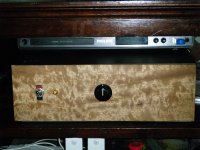
Case is old tape deck $10 from tip shop with homemade front panel in "tassie oak".
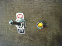
Alps pot.
Retro style controls.
Ahh, lets see now now , next project!
Budget MK1 special Lm3886 Juanjing amp board.
Upgrades include higher value input caps and resistors.Some resistors changed to carbon comp type.These mods suggested by linuxguru on "amazing ebay value" thread.
Transformer (to be upgraded ) and heatsink from defunct midi system.
Soft start and speaker relay boards.
Case is old tape deck $10 from tip shop with homemade front panel in "tassie oak".
Alps pot.
Retro style controls.
Ahh, lets see now now , next project!
Attachments
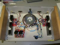
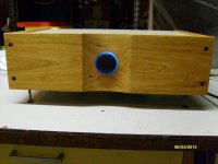
My First GC too, this is a Stereo LM1875
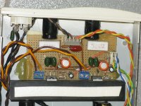
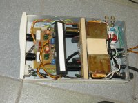
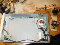
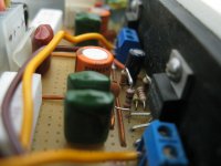
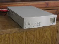
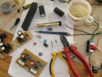
Hello this is my first GC i used to build ones when i was 16-17 (noy I'm 33 y.o.) but i didn't do something like this for around ten years from now, so.... Besides this is the first one that i build following all your advices (as much as i can), and taking care about most things you said as shared experience.
I'm SO SO happy for it, very very very happy
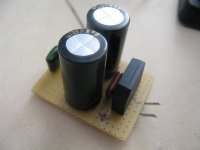
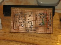
To build this one, I used an enclosure for an UPS (not working) of a friend of mine. So the space were limited, but good. The Trafos are 12V 50W for dicroic lights, I have two. Caps: 4700 + 4700 + 2200 + 470 (on LM1875 pins) per rail.
Wired board, regular schematic, and so on. I'm working to get experience and build a nice BPA woohoo...
Well, nothing more, it is just tha I LOVE how this sounds! A very clean sound my God! Better than the TDAs Amps i used to build. I had built on LM1875 before, and now i realise why i fell in love with them! I just hope to be faithful and don't fall inlove with the LM3886 LOL. Thanks everyone for the good advices you give, because this one is made and sound sooo great because of that, it goes for you then!
Hello this is my first GC i used to build ones when i was 16-17 (noy I'm 33 y.o.) but i didn't do something like this for around ten years from now, so.... Besides this is the first one that i build following all your advices (as much as i can), and taking care about most things you said as shared experience.
I'm SO SO happy for it, very very very happy
To build this one, I used an enclosure for an UPS (not working) of a friend of mine. So the space were limited, but good. The Trafos are 12V 50W for dicroic lights, I have two. Caps: 4700 + 4700 + 2200 + 470 (on LM1875 pins) per rail.
Wired board, regular schematic, and so on. I'm working to get experience and build a nice BPA
woohoo... Well, nothing more, it is just tha I LOVE how this sounds! A very clean sound my God! Better than the TDAs Amps i used to build. I had built on LM1875 before, and now i realise why i fell in love with them! I just hope to be faithful and don't fall inlove with the LM3886 LOL. Thanks everyone for the good advices you give, because this one is made and sound sooo great because of that, it goes for you then!
Attachments
-
 Gainclone_LM1875_01 004.jpg213.4 KB · Views: 627
 -
 Gainclone_LM1875_01 003.jpg199.5 KB · Views: 1,636
 -
 Gainclone_LM1875_01 001.jpg173.7 KB · Views: 1,713
 -
 Gainclone_LM1875_01 005.jpg144.2 KB · Views: 525
 -
 Gainclone_LM1875_01 007.jpg142.5 KB · Views: 656
 -
 Gainclone_LM1875_01_05.jpg102.9 KB · Views: 624
 -
 Gainclone_LM1875_01_06.jpg207.3 KB · Views: 379
 -
 Gainclone_LM1875_01_11.jpg256.6 KB · Views: 487
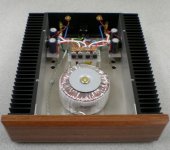
Wow!!!! 3886 amp project
Here's few pics for the build- Chipamp was fast in shipping and the circuit boards are really high quality. The build was done over five days. The chassis is 3/8" aluminum base with 1/8" lid and dadoed solid cherry sides. Note the blue illumination around the front panel volume control. The PS LED is cool! (Pot to be added later.) 330VA 25vac Avel with snubberized PS. Rail voltages at +/-35V
Connected it to my speakers, and it sounded better than my aged Hafler, which now has to be modded to regain its sound. Tight bass, clear upper ranges, Voltage sag under heavy bass riff was about 5 volts, but it sounds great.
I'll probably do another, but with multi chips per channel.
Attachments
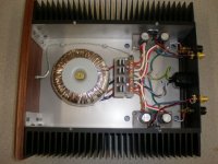
LM3886 Gainclone
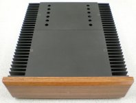
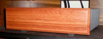
Here is my recently finished Gainclone. This is a garden variety implementation of Mick Feuerbacher's three resistor version (LM3886). I used a Caddock 22K resistor for feedback and the rest are Takman and Dale. Caps are Panasonic FC. 300VA 18V-0V-18V toroid and MUR860 diodes.
The heatsinks are massively over-spec at 300mm x 75mm x 45mm but they were quite cheap and the rest of the aluminium plate came from scrap. The front panel is varnished Western Australian Jarrah. The little silver dot in the middle of the panel is a 3mm silver tube bonded into the wood with a clear perspex rod bonded inside that. The whole thing goes through the front panel and a LED is fixed on the other side.
The amp has no perceptible hum and no switch on or off noises. I am very pleased with sound, especially compared with my DIY single ended MOSFET power follower and Pass BOZ preamp.
I have tried a stepped attenuator with this Gainclone and an "Optivol" LDR attentuator from Greg Ball (SKA). My preference is for the Optivol and I am about to build a simple FET buffer designed for the Optivol to see if/what difference it makes. I wanted to mount the volume control, whatever one I decide on, inside the Gainclone case, but I might have to make a small matching case for the Optivol, buffer and PSU.
Attachments
you need a real power supply!
Very nice but, Where is the power supply caps? I just see those small caps... you should build a REAL power supply like 20,000uf per rail. you will FEEL the bass.
Here is my recently finished Gainclone. This is a garden variety implementation of Mick Feuerbacher's three resistor version (LM3886). I used a Caddock 22K resistor for feedback and the rest are Takman and Dale. Caps are Panasonic FC. 300VA 18V-0V-18V toroid and MUR860 diodes.
The heatsinks are massively over-spec at 300mm x 75mm x 45mm but they were quite cheap and the rest of the aluminium plate came from scrap. The front panel is varnished Western Australian Jarrah. The little silver dot in the middle of the panel is a 3mm silver tube bonded into the wood with a clear perspex rod bonded inside that. The whole thing goes through the front panel and a LED is fixed on the other side.
The amp has no perceptible hum and no switch on or off noises. I am very pleased with sound, especially compared with my DIY single ended MOSFET power follower and Pass BOZ preamp.
I have tried a stepped attenuator with this Gainclone and an "Optivol" LDR attentuator from Greg Ball (SKA). My preference is for the Optivol and I am about to build a simple FET buffer designed for the Optivol to see if/what difference it makes. I wanted to mount the volume control, whatever one I decide on, inside the Gainclone case, but I might have to make a small matching case for the Optivol, buffer and PSU.
Very nice but, Where is the power supply caps? I just see those small caps... you should build a REAL power supply like 20,000uf per rail. you will FEEL the bass.
- Home
- Amplifiers
- Chip Amps
- Chip Amp Photo Gallery