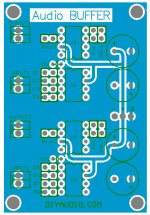
Audio Buffer layout
it is a chip based op amp plus buffer ic design.purpose for genus use.
the archetype url:
http://www.diyaudio.com/forums/showthread.php?postid=179554#post179554
here is my finished amp,to feed my hd495 headphone.it has fine lowZ performance.
http://www.diyaudio.com/forums/showthread.php?postid=362057#post362057
I transform it into PCB layout now.
Attachments
BOM list,
U1,U2- opa637 pdip
U3,U4- buf634 pdip package
*R1,R5- 220K 0.25W(for gain setting)
*R2,R6- 39K 0.25W(for gain setting)
*R3,R7- 1K 0.25W
*R4,R8- 47K 0.25W
*Ra1,Ra2- 1.5K 0.5W
Rb1,Rb2- (for buf634 BW setting)
CA1,CA2- 6.8uf/63V film caps or 33uf/35V aluminium cap
sch file attached")
U1,U2- opa637 pdip
U3,U4- buf634 pdip package
*R1,R5- 220K 0.25W(for gain setting)
*R2,R6- 39K 0.25W(for gain setting)
*R3,R7- 1K 0.25W
*R4,R8- 47K 0.25W
*Ra1,Ra2- 1.5K 0.5W
Rb1,Rb2- (for buf634 BW setting)
CA1,CA2- 6.8uf/63V film caps or 33uf/35V aluminium cap
sch file attached
Attachments
digi, you shuold add a cap (according to the datasheet of BUF634) between the output of the opamp and the inverting input. If you do this, your design will be more universal.
You also add a resistor for the BW pin so you can tune the bias current. Also for more flexibility.
OPA637 is not so good in low gain applications but this you know already? OPA627 is better. I see that the gain is 5.6 so a OPA637 will handle this but the pashe amrgin may be a bit too little. I would have chosen an OPA637 if the gain was 10 or more.
220k + 39 k is pretty high, both for noise (probably not an inssue) but I'm thinking of more of effects of stray caps and problem with stability. Why don't you lower these values to 10 k + 2.2k or even as low as 2.2k + 390? Since you have a buffer you really can "afford" these low values.
Add also decoupling at the supply pins, like 100 nF/63V Polyester, ceramic.
Avoid to use only a 6.8 uF film cap because they aren't so good high up in frequency.
I would also make the feedback path storter. Try to turn the feedback resistor.
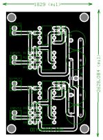
I would not have drawn the power traces under the IC's. I would have used this space for signal traces instead.
Strive to get the groundplane as "whole" as possible. Avoid traces which divides the groundplane.
Inspiration can be found here.
Just want to add that my headphone amp which is OPA627+BUF634, or AD8610+BUF634 is excellent. I have also tested OPA134 and I thought it did well also... so this buffer digi01 will be a success I'm sure.
You also add a resistor for the BW pin so you can tune the bias current. Also for more flexibility.
OPA637 is not so good in low gain applications but this you know already? OPA627 is better. I see that the gain is 5.6 so a OPA637 will handle this but the pashe amrgin may be a bit too little. I would have chosen an OPA637 if the gain was 10 or more.
220k + 39 k is pretty high, both for noise (probably not an inssue) but I'm thinking of more of effects of stray caps and problem with stability. Why don't you lower these values to 10 k + 2.2k or even as low as 2.2k + 390? Since you have a buffer you really can "afford" these low values.
Add also decoupling at the supply pins, like 100 nF/63V Polyester, ceramic.
Avoid to use only a 6.8 uF film cap because they aren't so good high up in frequency.
I would also make the feedback path storter. Try to turn the feedback resistor.
I would not have drawn the power traces under the IC's. I would have used this space for signal traces instead.
Strive to get the groundplane as "whole" as possible. Avoid traces which divides the groundplane.
Inspiration can be found here.
Just want to add that my headphone amp which is OPA627+BUF634, or AD8610+BUF634 is excellent. I have also tested OPA134 and I thought it did well also... so this buffer digi01 will be a success I'm sure.
thank you P-A,I will revise the layout in accordance with your suggestions.your smd version is wonderful BTW.
the part list is accounted for in my previous PCB layout(see attached pdf file).
here is the all parts schematic,the CA1/CA2 6.8uf caps is set up for the power rails.
beside the power circuit,you hardly find a cap in the all buffer circuit(the Cd1/Cd2 is added according to the suggestion of P-A).
enjoys
digi
falcott said:Hi digi,
I'm trying to work out where CA1 and 2 fit in on the schematic? (Yeah I know, I'm not so clever...
demogorgon said:your not alone Mr.Falcott.. it appears not all parts listed in your previous post are accounted for in the schematic?
regards
marius
the part list is accounted for in my previous PCB layout(see attached pdf file).
here is the all parts schematic,the CA1/CA2 6.8uf caps is set up for the power rails.
beside the power circuit,you hardly find a cap in the all buffer circuit(the Cd1/Cd2 is added according to the suggestion of P-A).
enjoys
digi
Attachments

Upupa Epops said:..... Look at PCB.......
Why is G RCT1 placed between R7 and R8?

Upupa Epops said:Answer is simply - I like symertic design
sometimes (often) an optically pleasing, aesthetic look works fine
Uli

- Status
- This old topic is closed. If you want to reopen this topic, contact a moderator using the "Report Post" button.
- Home
- Amplifiers
- Chip Amps
- audio buffer layout