Blew my socks off!Yep Clog... that's me. I added the flag after your post ;-).
The amp looks like pretty closed to "finished".... or not?
What is your opinion? Is it "okay" or "just fine" or "nice" or "superb" or...... did it blow your socks of?
Can't wait to hear more about it.
")
Yes I did. And of late I haven't had time to listen to either of them for very long!Redjr, afaik you built both the PA03 and Rudi's Symasym at about the same time. I'm very interested in your opinion on both amps. By coinicidence i also have Rudi's black beauty pcb's laying around. Still unpopulated.
Too busy with work, life and personal family matters that have taken me away from home lately. Hopefully, my schedule will slow down soon.Rick
Redjr, afaik you built both the PA03 and Rudi's Symasym at about the same time. I'm very interested in your opinion on both amps. By coinicidence i also have Rudi's black beauty pcb's laying around. Still unpopulated.
Yes Redjr plz plz
magic smoke ???
Episode 5
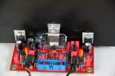
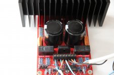
Inserted last parts into the board. As I said before the only hurdle was the exact mounting of the heat sink and the positioning of the LM4780. My 35W soldering iron has enough muscle to handle 99 percent of the joints but soldering parts to the ground plane took too much time. For these rare cases I used my antique soldering gun (oh horror!!!).
Okay now what. There it is in front of me. My first completed and professional looking amplifier board. To prevent disappointment perhaps it would be wise to stop here, frame it and hang it on the wall of my living. No won't happen.
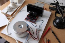
In his build guide Pavel advises to test it with a Variac which I don't have. Now it's time to put the bulb tester into practice. I decided not to put everything in a box because in case of sparks and smoke it would be all for nothing. So I mounted everything on a piece of chipboard.
For a while I was unsure how to connect the secondaries of my transformer but I got help. Recipe is “one winding with dot to ground and the other winding "no dot" to ground”. Again a teachable moment for me as I learned something about transformer phasing and the dot notation. I suppose it's easy to go wrong here because there are no clear markings on the dual secondary windings of my transformer. Well if you know where to look and know what to look at …… !!
Time to test the thing. I hooked up the bulb tester with a 25W bulb. Now don't laugh, newbee action here. I have read that big capacitors can explode so to be on the safe side I put safety goggles on. Seeing that my wife asked what on earth I was doing.
I have to confess that I had shaky hands when I put the mains plug of the PA03 in the bulb tester and flipped the switch. The bulb was flashing for two seconds and then dimmed down to such a level that it appeared to be off. After a short time the relays clicked and I thought……... job done. I left it on for about half an hour, no magic smoke came out. The bulb remained lukewarm. So I guess it's time to let the little bird sing its pretty song.
In the pictures: PA03 on testboard, all the parts on board (1) and (2),
To be continued ......
Episode 5
Inserted last parts into the board. As I said before the only hurdle was the exact mounting of the heat sink and the positioning of the LM4780. My 35W soldering iron has enough muscle to handle 99 percent of the joints but soldering parts to the ground plane took too much time. For these rare cases I used my antique soldering gun (oh horror!!!).
Okay now what. There it is in front of me. My first completed and professional looking amplifier board. To prevent disappointment perhaps it would be wise to stop here, frame it and hang it on the wall of my living. No won't happen.
In his build guide Pavel advises to test it with a Variac which I don't have. Now it's time to put the bulb tester into practice. I decided not to put everything in a box because in case of sparks and smoke it would be all for nothing. So I mounted everything on a piece of chipboard.
For a while I was unsure how to connect the secondaries of my transformer but I got help. Recipe is “one winding with dot to ground and the other winding "no dot" to ground”. Again a teachable moment for me as I learned something about transformer phasing and the dot notation. I suppose it's easy to go wrong here because there are no clear markings on the dual secondary windings of my transformer. Well if you know where to look and know what to look at …… !!
Time to test the thing. I hooked up the bulb tester with a 25W bulb. Now don't laugh, newbee action here. I have read that big capacitors can explode so to be on the safe side I put safety goggles on. Seeing that my wife asked what on earth I was doing.
I have to confess that I had shaky hands when I put the mains plug of the PA03 in the bulb tester and flipped the switch. The bulb was flashing for two seconds and then dimmed down to such a level that it appeared to be off. After a short time the relays clicked and I thought……... job done. I left it on for about half an hour, no magic smoke came out. The bulb remained lukewarm. So I guess it's time to let the little bird sing its pretty song.
In the pictures: PA03 on testboard, all the parts on board (1) and (2),
To be continued ......
Attachments
Measure some voltages while it is still powered up via the Bulb.
Check supply rails to ground and across each other.
Check output offset and output noise with the input shorted with a dummy/zeroOhm plug.
If all OK , power down.
What size of Mains fuse is fitted? Close rated, or enormous?
Now power up direct off Mains.
Check supply rails to ground and across each other.
Check output offset and output noise with the input shorted with a dummy/zeroOhm plug.
If all OK , power down.
What size of Mains fuse is fitted? Close rated, or enormous?
Now power up direct off Mains.
AndrewT suggested to measure some voltages.
Rails voltages +/- 34V so 68V across each other.
DC at output is approx 10mV, inputs shorted
AC at output approx 4mV, inputs shorted
Now I am wondering what are these figures telling me and why is it useful to collect them. Let me do some guesswork here. Feel free to correct me if I'm wrong. I like to learn something from this project.
The rails voltages give some indication about the proper functioning of my power supply. I guess the rails voltages have to mirror each other as in having the same positive resp. negative value. Furthermore they must not exceed the maximum value allowed for the LM4780. If I'm right the maximum is about 40 V. So to me these values seem to be okay.
Loudspeakers are intended to convert a varying input voltage to sound. So I guess they don't like DC voltages. I suppose high levels can burn out voice coils. But I wonder could it be that lower levels cause a deviation in the neutral position of the speakers voice coil. Is 10mV acceptable here ?? And what levels are not ??.
Now the noise figure puzzles me the most. With shorted input I was measuring the voltages at the LM4780 outputs. Now I suppose that the 4 mV I measured is the sum of all noise frequencies (hum + hiss) that are within the bandwidth of my DMM. To me this figure seems to be rather low. (????) But I wonder if my DMM is accurate at these low values.
New measurement
AndrewT, your comments - good or bad - are much appreciated. And what's more they invariably get me thinking. So when you wrote "The 4mVac for H+N is bad" my first reaction was I must have done something wrong because the PA03 is a renowned product made by a clever developer.
Then I remembered that back in the old days when my whole family was tinkering with tape recorders we bought a Leader AC millivoltmeter to adjust tape bias and that this almost forgotten instrument still has to be somewhere in the house. When I found it under layers of dust I quickly soldered some measuring clips together and did a new measurement. This time measuring with the Leader AC at output was approx 0,4mV, so ten times lower.
Attachments
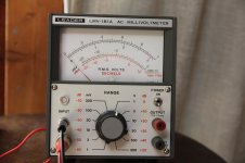
0.4mVac is much better.
Did your DMM measure on a 1.999Vac scale, or on a 199.9mVac scale?
I regularly get a reading of H+N = 0.0mVac which really means less than 0.05mVac for the bandwidth that the DMM has.
Some read 0.1mVac when on the bench.
Mounted in a Chassis I never get better and sometimes much worse. I keep working at it until the Chassis mounted is less than or equal to 0.3mVac. (0.3mVac is > +15dB ref 0.05mVac)
You are very close. Maybe you can try to get it a little bit lower.
0.3mVac is >96dB below 50W into 8ohms, i.e. silent on 90dB speakers at 500mm
Last edited:
The factor 10 difference between the two measurements still puzzles me. When the DMM is idling the screen displays about 0.000V. Does that mean that the measurement is on a 1.999Vac scale ???
During measurement it was in auto range mode, the most sensitive range is 400mV. Could it be an accuracy problem. For me the Leader as a dedicated Millivoltmeter is more trusted. Besides the fact that the outcome is much more favorable.
During measurement it was in auto range mode, the most sensitive range is 400mV. Could it be an accuracy problem. For me the Leader as a dedicated Millivoltmeter is more trusted. Besides the fact that the outcome is much more favorable.
@AndrewT, how ??You are very close. Maybe you can try to get it a little bit lower.
yes, 0.000Vac means the last digit is 0.001Vac and the specification probably looks a bit like this +-0.5% of reading +-3 digits.The factor 10 difference between the two measurements still puzzles me. When the DMM is idling the screen displays about 0.000V. Does that mean that the measurement is on a 1.999Vac scale ???
That particular specification could lead to reading from 0.001Vac to 0.007Vac for an actual voltage of 4.0mVac. You need a DMM with more resolution.
auto ranging is a problem. It can work very well when well designed.During measurement it was in auto range mode, the most sensitive range is 400mV. Could it be an accuracy problem. For me the Leader as a dedicated Millivoltmeter is more trusted. Besides the fact that the outcome is much more favorable.
But I find it slower than a set range and sometimes it will select a higher range than what could have been used leading to a lack of resolution.
My bench DMM and one of my portables are autoranging. My other two portables are pre-settable ranges.
All have a resolution of 0.1mVac at their most sensitive scale. But I don't trust my bench meter for very low signal it measures down to 100.0mVac very accurately and goes to Zero (for any voltage between 0.1mVac to 99.9mVac) when I know it is not zero.
It has an AC + DC scale that has resolution down to 0.01mVac but if there is any DC offset I think it reads the sum (it is an rms measurement) and again I don't trust it if I don't know if there is no DC in the voltage.
Fixed pre-setting for me.
moving cables,
@AndrewT, how ??
adopting rigorous twisting for ALL cable pairs,
changing to screen cable,
eliminating wiring errors,
sorting the grounding,
attenuating interference current,
moving an HBRR/HBRL to the correct side of a node,
etc .......
Last edited:
I almost fell off my chair !!!!
Episode 6
I left off when the bulb from the DBT (dim bulb tester) flashed and then appeared to be off. The relays clicked and I thought……... job done. Here in the forums I learned that at the end of your build there is either magic smoke or music. So I guess time to let the music out.
I don't know how you guys are handling this but for me a new amp has to earn some credits before I trust it with my valuable speakers. Over the course of time I gathered a lot of obsolete audio gear. From one corner came an old pioneer cd player, from another a Pioneer preamp and in the loft room I had a pair of dusty old B&W bookshelf speakers. I quickly connected the stuff but left the DBT in between. Perhaps you remember I'm in the category of the (over)careful types.
Okay time to flip the power switch. Everything seemed okay. Mmmmmmm, cd in the drawer, careful turn of the volume pot. Yes ………..there is music. Nice, now turn up the volume. Mmmmm…… that sounds strange. Stereo image wandering from left to right and back, some distortion, pumping sound, not good at all. What now ??
Let me tell you that's the effect of the DBT. I had completely forgotten to remove the DBT and I guess the strange effects I heard were the result of the DBT restricting the amp to draw enough current.
Now second attempt. For years now I'm addicted to computer audio. All my music is ripped to flac files and stored on a Synology Nas. As a consequence almost all my cd's are gone, given away, sold etc. Here with me I had just one cd to try out the PA03. Luckily track no 9 was one of my all time favorites. Toto's “Ï will remember”. A melancholic, kind of romantic song Steve Lukather wrote for the former drummer of Toto, who passed away a few years ago.
Now imagine I was alone on the loft, it was dead quiet and perhaps I turned up the volume a little bit too high, not full blast but well …… you know. The speakers were completely silent. And then out of the blue Toto's drum kit kicked in, loud, powerful, with authority and slam and I tell you I almost fell off my chair. Then the music flowed, with detail, staging, depth, you name it. I thought this can't be true, such a miniature amp. The pcb is just 10x20 cm, for a stereo amp !!!! It sounded like a much, much beefier amp. Next Track, Mariah Carey “Open arms”. Her voice as if she was standing there, flawless. And so track after track I continued and even when the music was so loud that my ears protested, the heat sink of the PA03 remained lukewarm.
Now these are just first impressions. And yes I know, the rest of the components aren't top-notch. And, for sure you'll tell me there is expectation bias here. I'm listening to a new product and what's more it's a product of my own hands. But to be true my expectations were not that high before. I had that feeling of “nice little thing but it can't be serious”. Now I think it is serious. Very much so.
I think it is time now top put the amp in a case. Then, if there is enough trust I will hook it up in my main stereo set.
To be continued ....
DBT is usually double blind test here.
and it was in the third paragraph where I saw "I had completely forgotten to remove the DBT" that I realised you were talking about leaving the biased amplifier still on the Mains Bulb Tester.
You are told repeatedly that the Mains Bulb Tester is for checking for incorrect wiring.
and it was in the third paragraph where I saw "I had completely forgotten to remove the DBT" that I realised you were talking about leaving the biased amplifier still on the Mains Bulb Tester.
You are told repeatedly that the Mains Bulb Tester is for checking for incorrect wiring.
Last edited:
- Home
- Amplifiers
- Chip Amps
- Newbee build: PA03 amp (LM4780)