I have multi way horns with active crossovers. No passive filters involved. High efficiency.
I DO have all impedance sweeps for all sections.
Does Trans-Amp work well for such a setup?
Usually you only need worry about the bass section in that case.
Post the impedance curves.
dave


A DYI forum with limits on sharing/learning, irrespective of depth-levels at least from time to time, it is either defective or a non-sense.
On the topic harmonic distortions on amps I found here a nice reading. Yes, it is from the "academic and industry valid reading" category... whatever this means; no pun intended. I hope this will be helpful for some of us understanding more details or controlling the designs and choice of components.
http://www.ti.com.cn/cn/lit/an/slyt133/slyt133.pdf
Picked from between lines:
- solid PS regulation
- proper decoupling caps (I guess some call them snubbers)
- proper thermal handling
- oversize if possible every component relative to your wished load-power to increase peak-power or peak-voltage handling (rating).
LM3875 datasheet is stating (or some only hinted) a mix of good features.
However this does not mean this IC is making a class of itself. If anyone knows names with similar set of parameters please let me know. Also if anyone knows better designed CS configurations (using discrete or ICs, old or new) please notify us giving a link or two.
At my end a minor contribution, I found something interesting for speakers just 3dB more sensitive: OPA548 can make an equally good 20W "mini"_Transamp. For "maxi"_Transamp I will try some old respectable hybrids and report.
Welcome any sharing of ideas, notes from other DYIers from the "in-depth" know to expand this topic. Exact further reading suggestions etc possible ?
Best wishes to all,
Ionmw
Last edited:
Hi Joe,
Even if we do not know internal details of LM3875, I think that if you can bring here the HD spectra on a modified CS amp (I understood you make/made around hundreds of them) to a VS configuration, then we can analyze 1:1 and draw some useful conclusions.
Maybe in VS configuration (aka "voltage") the internal operating point is struggling and therefore more contribution from 3rd order HD. Also, maybe, in CS configuration this IC takes better advantage of its features. Such situation would most likely hint to middle- driver section.
To be sure we should drive the LM3875 with a dedicated low-distorsion low noise preamp and measure again the HD for both external load configurations CS and VS. For dedicated low-distorsion / low noise preamp you can consider LME49710 or LME49720 (voltage input for low impedance sources) or any good dedicated-TIA opamp (current input for high impedance sources). Most likely you will need the first one if you want to do this test.
Ionmw
Noviygera, the data from the opening post of this thread: 100 mV input, 4 ohm load results in approximately 1V output and with a 8 ohm load => 2V.
You can expect: 16 ohm => 4V, 32 ohm => 8V, 62 ohm => 16V.
I can not even imagine what happens to the output voltage when the frequency of the input signal moves in and out of the high impedance part of the load.
You can expect: 16 ohm => 4V, 32 ohm => 8V, 62 ohm => 16V.
I can not even imagine what happens to the output voltage when the frequency of the input signal moves in and out of the high impedance part of the load.
@ Hi Noviygera,
your active-XOs must not deliver to the power-amp(s) the full range that includes aynthing near those resonance peaks. If you know them, tell us the bandpass details of your active XOs.
@ Hi Mark,
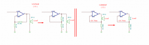
- I do not understand your question exactly, but what you describe it may be a boostrap follower configuration. This is also a trans-amp but described by a V_in=V_out condition. To unlock this, e.g. the CS configuration described here, the topology would necessarily need a current sensing resistor and load placed in NFB path. Please next time you address a topology question do it with a proper pic attached.
- see below attached pic (for more look at nearest library or online stores) for explanation of external operation point. Or use google for similar materials. I think that what Joe has applied here is best named as "transconductance" amplifier (="TCA") topology since the output is measured as [A]_out/[V]_in = 1/[Ohm]. This is different than Transimpedance amplifier (="TIA") which makes current-to-voltage conversion and therefore involves a specialized kind of OpAmps which have a current sensing (high-impedance) type of inputs. There are V-to-V and I-to-I topologies too. As you know, the V-to-V is the market norm.
- for audio devices too, the datasheet and standard tests only pure resistive (R) external components are used. Complex impedance components as C or L are placed on standard setups only if source& models require it, or if decoupling/filtering is needed.
your active-XOs must not deliver to the power-amp(s) the full range that includes aynthing near those resonance peaks. If you know them, tell us the bandpass details of your active XOs.
@ Hi Mark,
- I do not understand your question exactly, but what you describe it may be a boostrap follower configuration. This is also a trans-amp but described by a V_in=V_out condition. To unlock this, e.g. the CS configuration described here, the topology would necessarily need a current sensing resistor and load placed in NFB path. Please next time you address a topology question do it with a proper pic attached.
- see below attached pic (for more look at nearest library or online stores) for explanation of external operation point. Or use google for similar materials. I think that what Joe has applied here is best named as "transconductance" amplifier (="TCA") topology since the output is measured as [A]_out/[V]_in = 1/[Ohm]. This is different than Transimpedance amplifier (="TIA") which makes current-to-voltage conversion and therefore involves a specialized kind of OpAmps which have a current sensing (high-impedance) type of inputs. There are V-to-V and I-to-I topologies too. As you know, the V-to-V is the market norm.
- for audio devices too, the datasheet and standard tests only pure resistive (R) external components are used. Complex impedance components as C or L are placed on standard setups only if source& models require it, or if decoupling/filtering is needed.
Attachments
@ Mark,
I would answer your question with NO.
However, sorry, I am still unsure that fully I understand your point. Please try to reformulate your question.
Have you noticed the shunt 0.33ohm resistor to ground? This resistor is not part of NFB but forms a voltage divider for V_out. The AC component in this node plus DC-trim make a signal on (-) pin, which, when referred to the (+) pin, it should emulate phase and amplitude the original signal V_in (aka. the voltage on (+) pin referred to ground).
With or without this current sense resistor the results are not going to be alike. In my opinion it is a much different result when you put (-) at V_out, or at 0V or at some particular intermediate values.
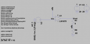
You can design, play and check yourself with the books using LTSpice or Tina-Ti, both free and powerful. Tina-Ti has a model for LM3875. Other programs are also available, likewise many book references.
I would answer your question with NO.
However, sorry, I am still unsure that fully I understand your point. Please try to reformulate your question.
Have you noticed the shunt 0.33ohm resistor to ground? This resistor is not part of NFB but forms a voltage divider for V_out. The AC component in this node plus DC-trim make a signal on (-) pin, which, when referred to the (+) pin, it should emulate phase and amplitude the original signal V_in (aka. the voltage on (+) pin referred to ground).
With or without this current sense resistor the results are not going to be alike. In my opinion it is a much different result when you put (-) at V_out, or at 0V or at some particular intermediate values.
You can design, play and check yourself with the books using LTSpice or Tina-Ti, both free and powerful. Tina-Ti has a model for LM3875. Other programs are also available, likewise many book references.
The standard feedback is a voltage divider and the 0.33 ohm resistor is part of the feedback loop.
A NFB could consist of a 24kohm and 1kohm voltage divider, which will give the amp a gain of 25. Now take Joe's 8ohm and 0.33ohm, this will also give you a gain of approximately 25 when measured between output and ground. Slightly less when measured over the 8ohm resistor.
When you replace the load with a resistor, as in Joe's distortion measurements, it no longer operates as a CS amp. Try the simulations and you will see what I mean.
@ Hi Noviygera,
your active-XOs must not deliver to the power-amp(s) the full range that includes aynthing near those resonance peaks. If you know them, tell us the bandpass details of your active XOs.
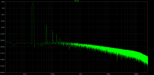
I'm not sure what you mean. The Mid and high were measured using Dayton WT3. No amplifier or crossover was in the signal chain. What you see are the actual full range imp sweeps. One for mid one for high.
@ Mark
To clarify, there are components inside de FB loop and there are components outside of FB, both being part of FB. The normal voltage VS amp topology does not have Load as part of feedback loop. The CS amp does. You talk of something else..., maybe ?
I guess you mean this (see pic).
NO. I think you again misunderstood something along the way. In both theory and simulations if you replace speaker(SP3) 8ohm with resistor (R7) 8ohm will still remain a CS amp. What this means to you? To me it means (see right of pic) that if I change R7 with anything in a range say from 4 to 35 ohm the current passing through R7 (="THE LOAD") will still have the same value (constant) and the voltage across load (SP3 or R7) will change as R7*I(R7).
What it means for you a Voltage amp? To me it means (see left of pic) that if I change SP1 or SP2 (="THE LOAD") the voltage output will stay constant and the current passing trough SP1 or 2 will be V_out/R(Sp1 or 2).
Ionmw
To clarify, there are components inside de FB loop and there are components outside of FB, both being part of FB. The normal voltage VS amp topology does not have Load as part of feedback loop. The CS amp does. You talk of something else..., maybe ?
I guess you mean this (see pic).
...When you replace the load with a resistor, as in Joe's distortion measurements, it no longer operates as a CS amp. Try the simulations and you will see what I mean.
NO. I think you again misunderstood something along the way. In both theory and simulations if you replace speaker(SP3) 8ohm with resistor (R7) 8ohm will still remain a CS amp. What this means to you? To me it means (see right of pic) that if I change R7 with anything in a range say from 4 to 35 ohm the current passing through R7 (="THE LOAD") will still have the same value (constant) and the voltage across load (SP3 or R7) will change as R7*I(R7).
What it means for you a Voltage amp? To me it means (see left of pic) that if I change SP1 or SP2 (="THE LOAD") the voltage output will stay constant and the current passing trough SP1 or 2 will be V_out/R(Sp1 or 2).
Ionmw
Attachments
Last edited:
Hi Noviygera,
See above post.
What I mean is that in CS amps the power delivered to load (speakers) is R*I^2 while for normal VS (voltage) amps the power delivered to load is V_out^2/R.
In CS topology the I is constant whatever impedance of speaker is at any given signal frequency. Therefore the P_load spectral characteristic will be in first approximation a 1:1 match to the Z-impedance plot of your speaker.
Think about it: this means that CS will emphasize signals with frequency belonging to resonances peaks or to spectrum regions of high(er) impedance (relative to the base 8ohm). For Trebles this is not a necessarily bad thing, but for Bass and Woofer it is. For this Dave warned and he asked for Z characteristics ... mainly for Bass/woofer, but you did not supplied. Also important: this spectral emphasis - specific to CS - can lead to clipping and speaker or amp destroction. Seeing values of peaks in your plots, I think active XO must do their job and provide exclusion of problematic frequency ranges for each driver.
In contrast Voltage (VS) amps will keep the voltage across load constant (aka regardless of speaker impedance, therefore regardless of signal frequency). This leads to conclusion that power delivered to load in VS amp is inversely proportional to value of speaker impedance at a given frequency. This translates so: peaks in Z:load are dips in P_load. Well... this will surely not destroy your speakers. The audio program is still effected by the missing information originating inside those dips.
If you have an active XO system, it also means to me those XOs are before poweramp. It also means that resonances are avoided (for VS amp that you have now). Same XO frequencies should be kept but keep in mind that active XOs for VS will tend to emphasize a high Z_load, while active XOs for CS must properly attenuate those spectral regions with high Z_load.
Problem is more complex (phase etc), and I defer here back to Dave to help you.
Greets,
Ionmw
... is a CS amp with a resistive load not a VS amp with a low resistance feedback? Why test a CS amp without the speaker/driver? Is there not an improvement to be had at the speakers/driver when using a CS amp compared to a VS amp?
... do you know how to test amp+speaker? I don't know.
I think there are technical tests... or listening tests. What you mean is probably a listening test? But then how can we exchange the relevant results??? Is it not better to read marketing, journals or proza from talented "writers" about their listening tests?
Do not forget, as Dave said, that HD or THD under a given level (say 0.2%) are all OK in listening tests. I would agree with him if HD would not be the source for IMD.
regards,
Ionmw
I agree here with Mark; the amplifier distortion should not differ between the CS and VS configurations. In VS, the feedback voltage is just taken from a separate voltage divider, whereas in CS the whole loading resistance is divided to give the same feedback voltage. As the resistance loading the amp is (essentially) the same, and the feedback signal is also equal, the IC cannot detect any difference between the cases and perform differently in any respect.Joe Rasmussen said:But here we have a mechanism that needs to be explained - why does the LM3875 have this profile when used in current mode when it does not have the same desirable traits when used in voltage mode. What mechanism is at play, how can it be explained? As I said, I have tried to bring this up a number of times and the 'talking heads' that could do something to decipher it, but since I am not in their good books, it gets dismissed as noise.
According to TI LM3875 data, THD is something like 0.01% at 1 kHz, not very far from your 0.023%. As I suggested earlier, the DC offset compensation scheme could be part of the explanation (i.e. a source of asymmetric distortion independent of signal level).
one point for analysis start - operation point at input CS and VS
Hi ETM,
I must agree with you but I cannot agree with Mark who boldly//oddly suggested to do "HD tests" with speaker... as the correct method. Really?
On amp topology, if this is what Mark meant, yes, ok. However back then I have asked myself... what is the difference to Joe's quite recent correct statement, that <<amp (whatever component, valves included too) will still be pushing amps at given voltage, either in CS as well in VS, identically>>... or a similar phrasing. I assumed by default that Mark must mean something else... now I see I was presumably wrong. He put the same idea but as a follow up question. So... was it a test? Or he did not thoroughly read the last 2-3 pages, maybe?
To your second idea. Do you believe that external DC-offset in CS would explain the puzzling HD measurements with odd-H plateau significantly under even-H plateau? How? This term is new to me: care to explain more what is an asymmetric distortion? Where can we read more on it. It certainly sounds as an interesting HD idea & lesson.
I recently asked Joe if he can measure again HD in CS and VS with one and the same amp. I hope he is setup to do it. Not yet answered...
This 1:1 analysis will help clarify if this peculiarity lies in the CSvsVS whatever differences that we do not see yet (and indirectly will raise the question why LM3875 reacts like this and other components not) or simply in Joe's amp technology. This is one reasonable starting point that I can see. Right?
Greetings,
Ionmw
ETM, thanks for the support and explaining. I don't think that the THD tells you very much and there are measurements of similar IC posted here at DiyAudio that are lower.
If you understand that both types of amps will act (almost) the same with a resistive load, Joe has mentioned this a few times, see how they differ when connected to a driver/speaker.
For CS, the driver is in the feedback loop and for VS, it is outside of the feedback loop. It is easy to see the different correction applied with varying resistance of the two types. What about capacitance and inductance, are they also differently corrected? My opinion is that they must be.
For me, the magic of the CS comes from the interaction between the amp and speaker. Replacing the driver with a resistor and the magic is gone.
Hi,Ionmw said:To your second idea. Do you believe that external DC-offset in CS would explain the puzzling HD measurements with odd-H plateau significantly under even-H plateau? How? This term is new to me: care to explain more what is an asymmetric distortion? Where can we read more on it. It certainly sounds as an interesting HD idea & lesson.
Even-order HD is asymmetric in that it makes the positive and negative half-waves asymmetric. Odd-order HD is symmetric in that the half-waves retain their symmetry (i.e. are mirror images of each other) despite the HD.
In addition to the desired DC, the offset trim resistors (1k worst case) also pass some AC to the load from the negative supply noise. This can generate asymmetric (even-order) distortion, but whether it is strong enough to explain the measurement, I cannot say (depends also on the pot position). Layout issues can also play a role, especially positioning of the supply wiring to prevent inductive coupling to the input.
- Home
- Amplifiers
- Chip Amps
- Joe Rasmussen "Trans-Amp" - 40 Watt Transconductance "Current Amplifier"