@ ETM,
Hi,
if I understand correctly the asymmetric distortion should contribute to first and odd harmonics. Right?
But Joe's measurements show less odd-H components.
Puzzling here is also another thing, Joe said this situation sounds more like Tubes. Well, I agree with you that if, asymmetric distors is in there due to DC-Trim, then yes it should sound Tubish because some (many?) Tubes indeed tend to have asymmetric distorsions - which perhaps come from using a single PS configuration. But, then mathematically this distorsion should increase the odd-H components, a prediction that is contrary to Joe's measurements.
However I am undecided on this DC-Trim asymmetric mechanism. I think, if Vee is leaking into signal, it should do it during entire cycle, not just 2-quadrants. In this case noise is leaking, yes indeed, independent of power. If it would leak only during 2 quadrants (asymmetric), it should logically be power dependent. Am I wrong...?
Maybe Joe will tell us soon, if for this clarification he can help us to remeasure VS and CS, or not.
regards,
Ionmw
Wrong. Asymmetric error produces even order harmonics (2nd, 4th etc.).if I understand correctly the asymmetric distortion should contribute to first and odd harmonics. Right?
Hi Ionmw, Vee is leaking during the whole cycle, if leaking is the right word?
Vee only drops when the output is negative. When the output is positive, Vee is stable and supplying (near to) no current. This is where the half cycle (rail and offset) behaviour comes from.
I will think about this.
Leaking smth into the signal necessarily means to me that I look at noise power (of anything "external": Vcc, Vee, ground etc) being unintended transferred to amplification path. This is normally power independent. Consider IMD of 1K signal (and its harmonics) with 100Hz noise (and harmonics from rectifier), would still show up as HD. The effect is to sharpen the higher harmonics peaks: amplitude wise (but not area wise) these peaks will show as reaching a plateau earlier than normal HD would do it. In this "power noise" sense we can have a bit of asymmetry too, because contribution to signal from leaked noise power occurred mostly from negative PS cycles.
The power dependent situation as you describe it in your example, and pertinent to Joe's solution without stabilization of rails, I would put it - for myself - into "modulation" kind of box and it is power dependent. Right?
So, for a "better sounding" amp we should leave the PS unregulated ???? I read many other people have a different opinion.
Greetings,
Ionmw
Last edited:
About differences in distortion in voltage or current amps. The main difference is, evidently, the work in current or in voltage, but the other important difference is that in the current amps the speaker and the wires are inside the feedback loop, and in the voltage amps are outside of the feedback loop.
In all the amps with feedback usualy the gain is defined with two resistors, in the current amps the speaker is one of the resistors, and the other the sensing resistor. In the voltage amps the resistors are in fact two resistors, and maintain the speaker and the wires outside of the feedback.
Some brands, as Deltec or Kenwood, have made amplifiers with a extra pair of wires that extended the feedback from the output to the connectors of the speakers, but this include only the wires, no the speakers inside the feedback.
Moreover of the work in current or in voltage, perhaps the different topology of the feedback can explain the differences in distortion.
It might be possible that DC-Trim may be imperfect. Combine this with some reasonable non-zero AMP+FB+Cables phase delay plus "intrinsic" HD at amp output. The result of (-) (+) sum might be asymmetric (input assumed centered at zero) and therefore give more amplification to the even orders of HD?
If true, a first trivial possible conclusion could be that odd-HD are not diminished, but instead the even-HD components are created//amplified.
A second possible conclusion, but an important one, would be that indeed even orders HD are indeed specific to this CS topology and DC-biasing. So, the general trend of its audio signature will be maintained, regardless of components. More general, as any CS topology would need this DC-Trim, it seems to become a general trend for the audio signature for all CFB CS chip-amps.
I am not sure. Could this theory be right?
Ionmw
P.S. anycase, Joe, would not be correct to measure HD of current through load, not as voltage referred to ground? I am just wondering, not sure if I am correct. It just sounds right to me, that in a CS configuration one should look at current through load. Not at the voltage at only one pole. False?
I am not sure. Could this theory be right?
It might be. I am a little snowed under, but I will investigate that possibility as soon as a I can. If indeed the odd orders are not changed and the even orders boosted, that crazily might not be such a bad outcome as there is a theory on the table that boosting even orders may in fact have a masking effect on the neighboring odd orders. Whichever is happening here, I will certainly find a way to seeing if the trim is the causality that explains it.
vote please
Hello,
I propose an ad-hoc temporary vote.
Suppose we learn(ed) how to make this circuit to produce even HDs and it is our choice to make it doing so more or less efficient, then what could be the "better idea"?
A. to shoot for as much even-HDs as our ears tell us to do? Whom may not give much importance to distinguish between instruments could easily vote this answer.
B. to shoot for as little of any sort, while flat-phase and TD-aligned until... GHz? Purists are welcomed to push this way.
C. there is an "enough" level (golden ratio) of even/odd HDs (ex. 10:1) to aim for? Those who designed for specs (and measured them at the end) might like to vote this answer, if they are pleased with their results.
Ionmw
Hi,
Even-order HD is asymmetric in that it makes the positive and negative half-waves asymmetric. Odd-order HD is symmetric in that the half-waves retain their symmetry (i.e. are mirror images of each other) despite the HD.
Hi ETM,
please help me a bit. I need a bit more solid and precise definition of how to discern HD odd-vs.-even via symmetry. Is there any symmetry rule for Hd-evens that HD-odds would not satisfy?
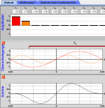
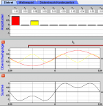
For example I have some difficulties to apply this simple method to the situation of asymmetric waveforms (assuming DC level=0).
First, I attached two simple situations... so what are the obvious symmetries. I see that within 0-Pi (halfwave) of H1, the HD-odds have mirror symmetry relative to Pi/2 axis while HD-evens do not have.
Analysis of an asymmetric waveform (relative to whatever angle of zero-crossing) according to this method still might indicate HD-odds, not HD-evens, if the zero-crossing happens at Pi. So this rule alone (for HS-odds only) appears not sufficient?
Because for this moment my simulation tool capability is not great, I cannot include the A0 term and simulate the output capacitor effect (level-shift to be DC-null).
Thanks!
Attachments
Indeed, vertical symmetry is phase dependent.
Thanks ... shift the second half-wave Pi to the left, sum must be zero for odds, non-zero for evens. If method is still wrong please help with correction.
This would explain easily the asymmetric distortion as sum of HD-evens only.
Thanks ... shift the second half-wave Pi to the left, sum must be zero for odds, non-zero for evens. If method is still wrong please help with correction.
This would explain easily the asymmetric distortion as sum of HD-evens only.
Important, or not?
Joe, for protections, what is generally your recommendation for this specific DYI project?
To avoid rush-in currents and generally to start using amps only after nominal working regime is in stable place, can one use relays to isolate load until this point in time (a la "voltage amps" style)? I am mostly concerned with woofer and mid speakers, cause their large inductance can produce huge voltage overshoot with CS amp (at the switching time but sharp signal transients will do this as well) destroying the Chip and possibily more.
Thanks.
^ Muting relays can be used with a CS, but preferably in parallel with the speaker, so that the amp is never without a load.
The LM3875 seems to have internal protection against voltage overshoots; where this is not the case, I have used protection diodes (e.g. 1N400*) from the output to both supply rails. Overshoots can occur if the amp is severely overdriven with an inductive load or the load is poorly connected but never in normal operation.
The LM3875 datasheet also says: "Supply Under-Voltage Protection, Not Allowing Internal Biasing to Occur When |V+| + |V−| ≤ 12V, Thus Eliminating Turn-On and Turn-Off Transients" Don't know how well it works here.
Not relevant, as the 470ohm/1W parallel to load is supposed to play this role... quasi. If load (speaker) is missing (bad connection) or if it fails, yes I am sure it will nicely do the intended job.^ Muting relays can be used with a CS, but preferably in parallel with the speaker, so that the amp is never without a load.
Either way, when the Relay will switch ON then it is quite possible to have an abrupt jump of current load (this current ramping is not filtered by input). A current change from a couple of tenths mA to say 1A in microsecond in ca. 8-10mH will create huge voltage overshoot possibly destroying the amp. Not to mention this kind of overshoot can create oscillations.
Temporarily my solution (sadly after burning one old hybrid chip without internal protection to voltage) was to place two Zeners series from Amp OUT to R_sense (or even to GND), that clips the voltage overshoots within permitted range of amp.
But in simulations there is a downside: these Zeners will affect the overall distortion figure (odds) also when the signal is relatively low.
Is there any other solution which helps fare better, still allowing 4-5sec of muting (at speaker side) until Amp (not only LM3975 case) is in safe operation?
Esa, a sketch is needed, maybe? You used simple diodes to rails, not Zeners to Gnd? What are the differences/advantages.. less distortion or something else?...where this is not the case, I have used protection diodes (e.g. 1N400*) from the output to both supply rails.
Yes, mind the phase of overshoots too for a given range of their frequency components...Overshoots can occur if the amp is severely overdriven with an inductive load or the load is poorly connected but never in normal operation.
So, a textbook case of oscillations in CS+woofer at driver's resonance. But I expect DYIers like me to experiment with their own components to check if they fit a project. To quantitate if an un-spec'd driver is good or bad for CS then one needs to characterize the Z of speaker in free air. A CS amp does look very attractive for this job, right? If it just... would not be so prone to oscillations due to high out impedance and fundamentally missing a fixed voltage gain... I can confirm, CS amps are not the most intuitive things. Or is a case of bad systematic "voltage education"
")
Good point for those who use this chip and who have speakers verified by others as good for CS. Maybe they do not need at all the start-up and shut-down muting relay. Likewise, I do not know how well it works. Can anyone confirm if biasing ramps up slow enough?The LM3875 datasheet also says: "Supply Under-Voltage Protection, Not Allowing Internal Biasing to Occur When |V+| + |V−| ≤ 12V, Thus Eliminating Turn-On and Turn-Off Transients" Don't know how well it works here.
Thanks.
Last edited:
- Home
- Amplifiers
- Chip Amps
- Joe Rasmussen "Trans-Amp" - 40 Watt Transconductance "Current Amplifier"