I can't quite see that working?
Thanks for your answer. I don't are a designer, this is the reson for need help, please, can you suggest other integrated that can work?
In the page have two integrated, the LA4425 and the TDA2002. The LA4425 have the pin 2 to ground, but I refered to the TDA2002.
...but I refered to the TDA2002.
That could/should work, the feedback that sets gain is external values, mainly resistors. Really, in basic theory, if you can put the speaker inside the feedback loop, it can become a transconductance/crurrent output amplifier.
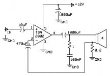
Thanks again. Please, is the attached scheme correct? Can you made some suggestion for improvement?
The trick here is that it is single ended power supply and I see that you have two blocking capacitors, so it looks OK to my eyes.
But... be careful, if you disconnect the speaker you are opening the loop of the amplifier chip (not designed for that), so you will need a permanent parallel resistor or else something is sure to go wrong. That parallel resistor effectively defines the output impedance (and also chews a bit of amplifier power). I would suggest a 100R permanent resistor, if the sensing resistor is 0.2R, then the max gain will be set to 100/0.2 = 500 (54dB max). You need to define that for safety.
Go back to Post #1 and you will see that I used 470R and 0.33R for current sense. I got an output Z of 270 and max gain of 58dB max. That's OK too.
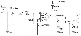
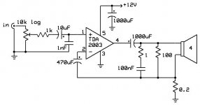
I have add the 100 Ohm resisto.. also some improvement in the input. Please, think you that all are OK, or I need made some other improvement?
I think you are almost there. The other thing is the Zobel network, I would put that, not to ground, but in parallel with the 100R resistor you just added.
Re the input low-pass filter, I would increase that 470pF to 1nF and once I have got the amplifier working, I would experiment with the 1K part of the filter, probably gradually increase it in value and settle on the value simply by listening only.
The Trans Amps work safe with full-range drivers, but the muti-way speakers need modifications in the crossovers.
Some brands, as Epos, have loudspeakers with the woofer straight connected to the amp, so work in full-range, the tweeter filtered with a simple capacitor.
Can work safe this type of loudspeaker with Trans Amps?
Some brands, as Epos, have loudspeakers with the woofer straight connected to the amp, so work in full-range, the tweeter filtered with a simple capacitor.
Can work safe this type of loudspeaker with Trans Amps?
That is now past history - but I am considering publishing a new Crossover for the Usher S520 that should be compatible with transconductance amplifiers like the one here, so stay posted.
An externally hosted image should be here but it was not working when we last tested it.
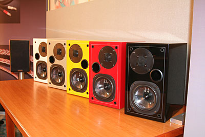
I have a pair of the Birch ones here - and of course aso available in Black, White and Red, even Yellow, all gloss finishes.
Please any help, there are some questions still bugging me and I am loosing focus because of them ")
1. for this LM3875 based amp in cs configuration, i.e. when output load impedance is not the "design recommended" matching at 8ohm or so, does the efficiency (e.g. amp/load matching) of chip suffers anyhow? Is there a new working point inside chip, or the same? If new working point will be the case, then how can we estimate (audio) performances and the overall behavior short and long term? Anyone can make additional general comments in regards to internal efficiency (i.e. output impedance, load matching topics) of Voltage designed chips but used as CS-configuration instead?
2. what about catalog specs for these chips? Still the same? Example: THD at a given power stay the same? Or it improves.. or it degrades..? What would be the correct reasoning when we attempt an evaluation?
Thanks,
Ionmw
Please any help, there are some questions still bugging me and I am loosing focus because of them
Don't be discouraged, but the whole concept of current is up-side-down in many respects, one is that voltage is so intuitive to our thinking and current is not, a bit like a negative image of a photo will confuse you because everything is reversed.
1. for this LM3875 based amp in cs configuration, i.e. when output load impedance is not the "design recommended" matching at 8ohm or so, does the efficiency (e.g. amp/load matching) of chip suffers anyhow? Is there a new working point inside chip, or the same? If new working point will be the case, then how can we estimate (audio) performances and the overall behavior short and long term? Anyone can make additional general comments in regards to internal efficiency (i.e. output impedance, load matching topics) of Voltage designed chips but used as CS-configuration instead?
In terms of maximum power, there is no fundamental difference, you still have to swing voltage and current, the only difference is that you are pushing current through a load and the load produces the voltage. The more intuitive voltage, the current is a function of the load, but with current, voltage is a function of the load. So twice the voltage will appear at 8 Ohm compared to 4 Ohm. Hence, four times the power into 8 Ohm. But the amplifier still clips when it runs out of volts in the power supply - no difference there. So 40 Watt max/approx is what it always will be.
2. what about catalog specs for these chips? Still the same? Example: THD at a given power stay the same? Or it improves.. or it degrades..? What would be the correct reasoning when we attempt an evaluation?
In terms of overall THD is not be all that different, very respectable at all times. But with the LM3875 in current mode, the spectral distribution changes dramatically and is more even order that odd order, in fact they are shelved differently with the nastier odd order is suppressed on the lower shelf. This makes for a sweeter sounding amp, less SS and more akin to a tube amp, even if all that is an over-generalising. Bottom line, it sounds different and for the better and that distortion pattern/profile is the key.
10 Watt THD 0.023% & THD+N 0.028% - very respectable indeed. You can see that odd orders are the lower shelf when you plot them. Does this affect the sound? You bet.
I do recommend that you read Current Source Amplifiers / Full Range Drivers by Nelson Pass.
In the end, it is about making speakers that are compatible, that is the key to getting the most benefit out of current drive. Over time I hope to make more designs capable of taking advantage of that, I already have the Elsinore Mk6 loudspeakers as a DIY project out there, got the DIY rebuild of the Usher S520 coming up soon (that is my plan at this stage) and hope to build on that. There is also plenty of fullrange drivers mentioned by Nelson Pass and applying the info that he supplies.
As I keep saying, when you are talking about current driving, then you can't talk about it without talking about speakers. Voltage drive is a dumb sport comparatively.
PS: Current is what makes a cone move, motors are current devices, coils and magnets. But perhaps the greatest pay-off is a lower noise floor - and this is a topic that is yet fully to be discussed.
Last edited:
Thanks Joe.
Any other wants to help here?
Look at the above questions 1-level, or a couple more, deeper. What is the internal chip mechanism specific of cs-configuration (assuming same pure resistive 8ohm load) to make the chip to generate less THD?
Take any audio-power chip (some say we have about 1500 options from 80's to date) in cs-configuration: should we a-priori estimate that THD will decrease 60% vs. the "voltage specs"? Based on what theory we assign this to the chip component in cs-configuration, and NOT to the implementation (amp-engineering, speakers, etc.).
If we can measure something (ex. THD) we should be able to supply a theory that supports this measurement, i.e. why some factors contributing THD were minimized. To answer this question we should be clear which factors THD "inside chip" will contribute more. Any help from audio-electronics guys?
Besides my wish to understand how to control this cs design, I am really curious why no other chip but the LM3875 has the "best sound". High-end audio electronics professionals (Marantz, Sansui, Pioneer, Sony, Technics as few examples) use consistently Sanyo (STK) or Sanken components, as starting point. Oddly enough, TI was never praised or used as much, yet LM3875 is old enough. It is praised (almost CULT) by DYIers but I still did not heard//read of it being used in any high-end professional unit. I am therefore just curious and want to understand more in depth.
As I said, my promise is to test this with both Sanyo STK-s or Sanken SI-s. Target for measurement 10W in 8ohms, using a well regulated PS and same amp. If needed I will build adapter to use LM3875 chip too. What needs to be done, meanwhile, is to really discuss and agree what parameters and mechanisms are relevant and worth to be measured and analyzed.
Who helps a good start, please? Or shall I plan this in-depth talk into a separate thread with another circle?
Thanks,
Ionmw
I will speculate. Measured distortion goes down because speaker drivers are current devices. You are no longer using the speaker impedance as an IV converter when you use a current amp.
Do note that THD is a useless measure. Althou Joe posted such a meaningless THD number he also posted a spectrum graph which does give you some useful information.
dave
Do note that THD is a useless measure. Althou Joe posted such a meaningless THD number he also posted a spectrum graph which does give you some useful information.
dave
Dave, I just want to reply here to an previous answer (recommendation for read) from you: I think that I have an understanding how to make variable transimpedance practically work It is indeed more elaborate than Joe's, I see also more usage.
What is still unclear: why would be acoustically better at mid-lower lower powers? You use the word "predating". Well, this implicitly means a lot of much higher expectations.
In my opinion if engineered correctly using same core-components I find difficult to see any audio advantage over Joe's "simpler" implementation if one and the same amp-technology and speaker setup is used.
Greetings,
Ionmw
It is indeed more elaborate than Joe's, I see also more usage. What is still unclear: why would be acoustically better at mid-lower lower powers? You use the word "predating". Well, this implicitly means a lot of much higher expectations.
In my opinion if engineered correctly using same core-components I find difficult to see any audio advantage over Joe's "simpler" implementation if one and the same amp-technology and speaker setup is used.
Greetings,
Ionmw
I will speculate. Measured distortion goes down because speaker drivers are current devices. You are no longer using the speaker impedance as an IV converter when you use a current amp.
Do note that THD is a useless measure. Althou Joe posted such a meaningless THD number he also posted a spectrum graph which does give you some useful information.
dave
I note that THD measurements in my understanding should be made with pure-resistive loads if we want to be correct and produce results compatible to datasheet.
Therefore I admittedly suppose that Joe did measured THD correctly.
I do not understand the word "meaningless"? At least in this aspect I see Joe's positive contribution: his measured results show a 60% improvement vs. the datasheet. Why positive? Well, contrary to expectations I do not evaluate the values themselves, but fact is that not many here present their measured results. We should appreciate anytime somebody brings to this DYI table more than proza, always proza again and again. Again said, I trust these measurements to be done the correct and professional way... and I do not even inquire this detail when ... it's Joe. How to clarify... when you have the right instruments and you have a business you also tend to learn to operate them correctly
Or else is a profesional suicide action 2nd note: if we disregard one of the few universal metric that industry and component makers give us (aka THD) then... what we are left with? Operating voltages and form factors? I think the marketing people will die next before what you say is true
3rd note: why THD not worth of attention, technically speaking?
Cheers,
Ionmw
I do not understand the word "meaningless"?
THD -- the single number -- below a certain point has no correclation with the sonics. It is useless, meaningless, tells you nothing, is misleading.
I trust these measurements to be done the correct and professional way
I have no question about the techniques used. A technique that used the real speaker impedance -- amplifier should never really be considered separatly from the speaker ot will be used with -- would be better. Using something other than a sin wave would also be nice.
2nd note: if we disregard one of the few universal metric that industry and component makers give us (aka THD) then... what we are left with?
If it is meaningless what is the point? Do you judge the flavour of ice cream from the colour?
3rd note: why THD not worth of attention, technically speaking?
See above. If you are not given a distortion spectra -- as Joe did -- then it is just so much gobbledegook.
dave
Several high-end LM chip-amps have been build. Gaincard from 47 labs and Model 10/Concentra from Jeff Rolland are a good place to see what is achievable.
My personal take on Gaincard and Gainclones (i.e. NOT transamp): the 47Lab and some DYIers needs to make up their minds. For 47Lab: to release or not the definitory detail of Gainclone (I read it is still seen like a black box of mystery). The others, some DYI-ers, seem to still do not understand how to pick up in a logical manner another better chip and at the same time to justify the use of name Gainclone... not the trivial name "standard configuration" as described in datasheets or even 100% explained in 101 of solid-state majors decades before the born of the CULT.
You mean that big brands choose to blatantly disregard all qualities of LM3875.. or they and choose to stay in misery with their choice of more expensive (or even equally expensive) parts? OK you are right. My question... all of them made this choice during the last... 20 years or so???
In strong contrast, here on this Thread, the topic is MUCH clear: Joe presented a CS configuration. This is clearly defined and that is what I appreciate most.
Cheers to you too,
Ionmw
Last edited:
- Home
- Amplifiers
- Chip Amps
- Joe Rasmussen "Trans-Amp" - 40 Watt Transconductance "Current Amplifier"