For usage in a Philips MFB replica : 3ch LM3886 based poweramp with DC protection and onboard buffercaps. Component side, 80 x 100 mm.
Solder side
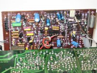
Partially assembled
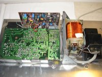
3ch substractive xover, limiter and mfb correction logic, component side.
Solder side:
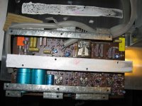
Fits snugly in the original transformer compartment
An externally hosted image should be here but it was not working when we last tested it.
Solder side
An externally hosted image should be here but it was not working when we last tested it.
Partially assembled
An externally hosted image should be here but it was not working when we last tested it.
3ch substractive xover, limiter and mfb correction logic, component side.
An externally hosted image should be here but it was not working when we last tested it.
Solder side:
An externally hosted image should be here but it was not working when we last tested it.
Fits snugly in the original transformer compartment
An externally hosted image should be here but it was not working when we last tested it.
Last edited:
Good day to you,
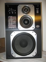
Re- Phillips Motional Feedback Amplifier Speakers [22 AH 587]
Please can you help, I am in need of professional help in identifying the loss of amplification and renewing the failed component. I can supply more information of the fault, a PDF of my original instruction book and photos of the pc board etc.
In return I am sure I can offer to help with my profession being a Heating and Electrical Engineer with over 30 years in this, although I did serve my time as a Joiner and could advise on this.
If this, like me is outside of this knowledge and you know someone more knowledgeable, would you kindly pass this message over.
Regards Michael
The green Standby and the red Operating neon indicators are working, and a little sound (maybe it is coming from the pre-amp). I can see there is a 24v relay on the PC board and my thoughts are to test for resistance through the coil and check that there is voltage to this coil when the operating indicator is On, and report back on this (the other speaker has had a new amplifier fitted last year)?
Attachments
-
Information 1..pdf237 KB · Views: 136
-
Information 2..pdf303.3 KB · Views: 100
-
Information 3..pdf745.1 KB · Views: 102
-
Information 4..pdf391.6 KB · Views: 102
-
Information 5..pdf284.3 KB · Views: 99
-
 IMG_5462s.jpg208.5 KB · Views: 359
 -
 IMG_5457s.jpg100.9 KB · Views: 318
 -
 IMG_5445s.jpg252.1 KB · Views: 322
 -
 IMG_5437s.jpg216.5 KB · Views: 361
 -
 IMG_5431s.jpg98 KB · Views: 414
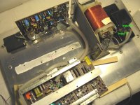
Have you checked the basics ?
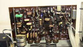
You have to start somewhere... so I would check initially that the minus 35 and plus 35 volts rails are present on the output stage and that the output (before the speaker relays) is at zero volts. There are two power amps that I can see. On for the woofer and one for the tweeter. Check both.
If that is OK then you need to check all the rails as a starting point. Start at the input stages and check working from input to output.
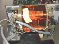
Mains Transformer Voltage Readings Between;
A = 234 vac Input source
B = 116 vac
C = 116 vac
D = 25.6 vac
E = 25.6 vac
F = 0 vac Input source?
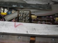
Relay; resistance across coil .576 KΩ.
With no voltage until the red Operating neon indicator is on; then giving 10 vac.
Resistance across a paired contacts was .000 MΩ whilst 10 volts were present.
Notes: my meter did not identify DC only AC (maybe I needed to set the range?).
F indicates another input source?
Relay indicates 24 vdc (I haven’t seen contacts illustrated on the relay cover like these before, I don’t understand the working/movement of them?).
A = 234 vac Input source
B = 116 vac
C = 116 vac
D = 25.6 vac
E = 25.6 vac
F = 0 vac Input source?
Relay; resistance across coil .576 KΩ.
With no voltage until the red Operating neon indicator is on; then giving 10 vac.
Resistance across a paired contacts was .000 MΩ whilst 10 volts were present.
Notes: my meter did not identify DC only AC (maybe I needed to set the range?).
F indicates another input source?
Relay indicates 24 vdc (I haven’t seen contacts illustrated on the relay cover like these before, I don’t understand the working/movement of them?).
Attachments
Good day to you,
Re- Phillips Motional Feedback Amplifier Speakers [22 AH 587]
Please can you help, I am in need of professional help in identifying the loss of amplification and renewing the failed component. I can supply more information of the fault, a PDF of my original instruction book and photos of the pc board etc.
In return I am sure I can offer to help with my profession being a Heating and Electrical Engineer with over 30 years in this, although I did serve my time as a Joiner and could advise on this.
If this, like me is outside of this knowledge and you know someone more knowledgeable, would you kindly pass this message over.
Regards Michael
Michael, you could also try to register on the Dutch forum (enough people there can also communicate in english) : MFBfreaks.com • Forumoverzicht
I know several aspects of this type MFB have been handled over there..
Cheers,
Edwin
If you are going to repair this then you have to be reasonably confident working your way around a circuit diagram and being able to locate parts.
Those voltages sound OK but one will be a plus voltage and the other minus. Are the two fuses OK (marked on diagram next to the caps) ?
You then need to confirm that the output stages (only one shown here) are receiving that supply and also that the output point is at zero volts as shown on the diagram.
Attachments
Thank you for your help, I am just updating you, have ordered a multi-meter to test the Capacitors (will be testing those you have mentioned and testing them on board), it could be into October before I receive this, and then make a start. http://www.amazon.co.uk/dp/B00JEWAS0W/ref=pe_385721_37986871_TE_item
https://www.youtube.com/watch?v=TFa6JfVu3B4
I found this very interesting https://www.youtube.com/watch?v=LZ49GCnf0V4
https://www.youtube.com/watch?v=TFa6JfVu3B4
I found this very interesting https://www.youtube.com/watch?v=LZ49GCnf0V4
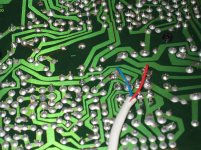
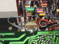
") All the evidence will be there in the form of the voltage readings.
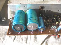
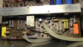
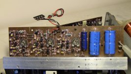
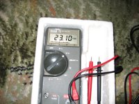
All the evidence will be there in the form of the voltage readings.I have replaced all the Philips Blue Electrolytic Capacitors 18 of them; I have tested the old ones and 13 of them still had good readings using a capacitor tester. I replaced the Relay as well, it is still no better.
Chart of Blue Electrolytic Capacitors.
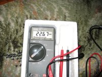
The dc voltage at the relay, 22.67 – 23.10 vdc after 3 minutes of activation the voltage stabilised.
Chart of Blue Electrolytic Capacitors.
The dc voltage at the relay, 22.67 – 23.10 vdc after 3 minutes of activation the voltage stabilised.
Attachments
-
 IMG_0246m.jpg694.2 KB · Views: 223
 -
 IMG_0248m.jpg737.2 KB · Views: 223
 -
 IMG_0253m.jpg756.3 KB · Views: 238
 -
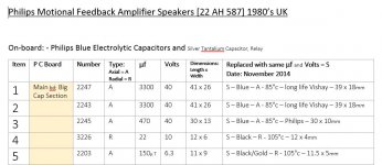 Chart of Blue Electrolytic Capacitors a.JPG86.9 KB · Views: 188
 -
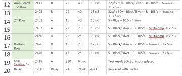 Chart of Blue Electrolytic Capacitors c.JPG89.2 KB · Views: 68
 -
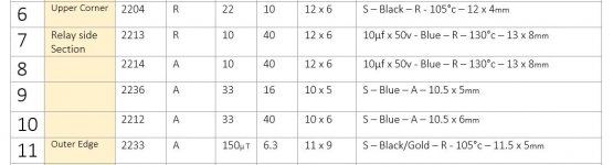 Chart of Blue Electrolytic Capacitors b.JPG58.4 KB · Views: 178
 -
 IMG_5708 m.jpg398.8 KB · Views: 81
 -
 IMG_5709m.jpg384 KB · Views: 78
 -
 IMG_5713m.jpg465.6 KB · Views: 102
 -
 IMG_5715m.jpg383.9 KB · Views: 58
Last edited:
Many weeks have past since this was last on the go...
I can see you have been busy replacing the caps but the only way to fix this is to gather the evidence of a few crucial voltage checks as was outlined earlier.
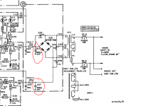
Look back at post #10. Those three voltages measured at those exact locations will tell you much. There must be the - and + 35 volts present on the transistors and the centre output point I circled must be at around 0 volts DC. I don't think you got that far before. Also, with the amp OFF you can do a resistance check of those 0.33 ohm resistors that feed from the output transistors to the speaker output (3260 and 3263 on that diagram above). If either is open circuit then its a sure bet that the output transistors have failed short circuit.
I can see you have been busy replacing the caps but the only way to fix this is to gather the evidence of a few crucial voltage checks as was outlined earlier.
Look back at post #10. Those three voltages measured at those exact locations will tell you much. There must be the - and + 35 volts present on the transistors and the centre output point I circled must be at around 0 volts DC. I don't think you got that far before. Also, with the amp OFF you can do a resistance check of those 0.33 ohm resistors that feed from the output transistors to the speaker output (3260 and 3263 on that diagram above). If either is open circuit then its a sure bet that the output transistors have failed short circuit.
Hello Mooly, and many thanks for your help it is much appreciated!
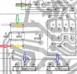
To prevent no misunderstanding I am going to check with the following procedure; I have submitted a drawing with probe connection points identified each check by colour.
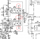
1. dcv readings probes attached to ends of each cap, on cap 2243 and 2247.
2. dcv readings probes attached to connection points +35v of 6221 and -35v of 6222, indicated blue.
3. mv reading probes attached to connection points indicated red, polarity connection not important?
4. Quote “the centre output point I circled must be at around 0 volts DC” indicated green.
5 readings 240v connected?
5. Resistance Ω readings on resistors 3260 indicated pink and 3263 indicated gold; polarity connection not important?
2 readings 0 volts connected? Regards Michael
To prevent no misunderstanding I am going to check with the following procedure; I have submitted a drawing with probe connection points identified each check by colour.
1. dcv readings probes attached to ends of each cap, on cap 2243 and 2247.
2. dcv readings probes attached to connection points +35v of 6221 and -35v of 6222, indicated blue.
3. mv reading probes attached to connection points indicated red, polarity connection not important?
4. Quote “the centre output point I circled must be at around 0 volts DC” indicated green.
5 readings 240v connected?
5. Resistance Ω readings on resistors 3260 indicated pink and 3263 indicated gold; polarity connection not important?
2 readings 0 volts connected? Regards Michael
Attachments
That seems basically OK.
You have confirmed the + 35 and - 35 volts are present at the output transistors. Thats good.
The geen arrows... are you are seeing around zero volts at that point (with it all switched on) ?
Something extra to check while its still powered up. There should be a tiny (around 40millivolts or so) voltage across each of those two resistors. Make sure to measure across them. The absolute value is unimportant as long as something in the 20 to say 70 millivolt region is present.
If all that checks out OK and that small voltage is present then we need to look at the other stages before the power amp section.
If that tiny voltage across the resistors is high (say 30 volts) the resistors are open circuit and the power transistors will be faulty too.
If the tiny voltage is not present then just for confirmation check the resistors on the ohms range on your meter.
To do that switch it all off. Set your meter to a low ohms range. As a check, if you now short just the probe tips together then the display should read around 0.00, depending on the resolution of the meter it might show something like 0.1 etc which would be the actual resistance of the meter leads.
Yes, that's it. Polarity of the meter leads doesn't matter.
When you are measuring voltages no harm will come to either the meter (as long as it is set to any voltage range) or the circuit (as long as the probes don't slip and zap something).
When the meter is set to ohms or diode check then it must only be connected to a circuit that is switched off.
Current ranges on the meter we wont be using.
- Status
- This old topic is closed. If you want to reopen this topic, contact a moderator using the "Report Post" button.
- Home
- Amplifiers
- Chip Amps
- Philips 22AH587 replica modules