Removed the resistor (3509/180Ω x 0.25 watt. Safety type) looks charred and was raised as you said, and professionally formed to fit, I might add. It read 11 mΩ, tested opposite ends 0Ω and 0Ω at either end now.
I noted a distinctive brown band to one end, does it matter which end this goes?
I cannot identify a safety type, please can you assist
I would prefer to buy from CPC Farnell there is something wrong with their search I cannot re-find this, just as well I had it saved.
RS have 2.
Farnell element 14 have 5.
Do you know where to buy
Resistors can go either way around. I was going to say something was amiss with the measurement... you mean 11 Meg (million) ohms. Milli would be a short.
I would really recommend just trying to get this up and running first before ordering specialised parts. Safety resistors probably come under "fusible" resistors. They are not very common but Philips loved to use them liberally in many products.
Just looked. Both CPC and Farnell don't list 180 ohm fusibles.
I would stick a 180 ohm carbon or metal film in there and see what else is wrong first.
That's fine...its just that I don't want you ordering one off parts when the original fault is still present plus the fact that either of those two transistors in the regulator just might be damaged too.
I even had a quick look at the circuit again to see if there was a 180 ohm or thereabouts in some other non vital location that you could have just swapped out as an instant check of the regulator. If you have any resistor in the 150 to 470 ohm range then we can try one of those.
I even had a quick look at the circuit again to see if there was a 180 ohm or thereabouts in some other non vital location that you could have just swapped out as an instant check of the regulator. If you have any resistor in the 150 to 470 ohm range then we can try one of those.

Temporary replaced (3509/180Ω x 0.25 watt, fusible resistor) with a 200Ω x 0.25 watt, none fusible resistor.
Re-Test results inside brackets in bold as in Post 28: dcv readings; probes attached to connection points, indicated brown, (38.8v).
Resistance Ω readings; on safety resistor 3300 indicated pink (33.7Ω).
Re-Test results inside brackets in bold as in Post 36:
A= something higher than PLUS 30 volts DC (+ 31.75v)
B= around 21 volts DC (+ 18.86v)
C= around 21 volts DC (+18.20v)
D= higher than MINUS 30 volts DC (- 33.4v)
E= around MINUS 21 volts DC (- 20.51v)
Last edited:
That all looks reasonable and show the rails to be OK. So we are back to a state where we can work on it.
Right back at the start you mentioned there was faint sound and crackles when operating controls. Is that still the case ? If so can assume that the speaker relay is closed (as it should be) and all the speakers are connected to the appropriate amplifiers.
Assuming that is the case then try and follow this logic...
There are three separate power amplifiers in the device, one for the bass speaker, one for mid and one for the tweeter. A fault with any should prevent the relay closing. If you can hear any noise at all from the speaker drive units then there is no problem with the relay and its circuitry.
That means we need to be looking further toward the inputs to see where the audio is disappearing... and without a scope you have to use other methods.
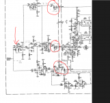
The audio to each power amp comes from a common source.
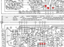
The point I have marked with an arrow is the input to the filters that split the audio 3 ways. If you turn the levels down (the three circled pots) near to but not quite to zero (to begin with) and if you touch the arrowed point with a metallic screwdriver then you should hear loud noise (hum/hash) from the speakers.
We need to determine if the problem is before or after this point.
I see there are a lot of switches and so on in the audio path. Are you sure they are all correctly set ?
Second picture shows the input switches. These need to be correct to pass audio. As drawn only the right input is closed and will allow audio to pass.
Right back at the start you mentioned there was faint sound and crackles when operating controls. Is that still the case ? If so can assume that the speaker relay is closed (as it should be) and all the speakers are connected to the appropriate amplifiers.
Assuming that is the case then try and follow this logic...
There are three separate power amplifiers in the device, one for the bass speaker, one for mid and one for the tweeter. A fault with any should prevent the relay closing. If you can hear any noise at all from the speaker drive units then there is no problem with the relay and its circuitry.
That means we need to be looking further toward the inputs to see where the audio is disappearing... and without a scope you have to use other methods.
The audio to each power amp comes from a common source.
The point I have marked with an arrow is the input to the filters that split the audio 3 ways. If you turn the levels down (the three circled pots) near to but not quite to zero (to begin with) and if you touch the arrowed point with a metallic screwdriver then you should hear loud noise (hum/hash) from the speakers.
We need to determine if the problem is before or after this point.
I see there are a lot of switches and so on in the audio path. Are you sure they are all correctly set ?
Second picture shows the input switches. These need to be correct to pass audio. As drawn only the right input is closed and will allow audio to pass.
Attachments
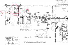
Looking at the input switches in your second picture; please note, I can say all are switched on otherwise the sound, wouldn’t pass to the speakers, the sound is via the preamp only, kindly see post 23?
I need to check if there is a connection point between 2436 and 2437, could I connect individually on these instead?
Please identify the pots, kindly see post 6 mid photo lower part, showing 3 adjusters and upper part, showing 4 adjusters, any of these. To undertake this test, connect the 4 internal speaker box leads and mains, only (it’s a pity to have to alter these settings, is there any components I could check before)?
Ah, I thought they were user adjustable controls, not presets. I grew up with potentiometers having the wiper drawn as an arrow, and presets as a 'flat'. I suspect the / (slash) alongside denotes a preset.
Just test with them set as they are. Just gently touch the metal blade of a small screwdriver on that point. Don't short it to anything and to begin with make sure that you are not touching the blade either (could cause a lot of hum and noise). See if it clicks. If its all pretty quiet then lightly touch the blade with a finger. Don't be touching anything else with the other hand though (these is no shock hazard... its for other reasons why not)
Just test with them set as they are. Just gently touch the metal blade of a small screwdriver on that point. Don't short it to anything and to begin with make sure that you are not touching the blade either (could cause a lot of hum and noise). See if it clicks. If its all pretty quiet then lightly touch the blade with a finger. Don't be touching anything else with the other hand though (these is no shock hazard... its for other reasons why not)
There is a connection point between 2436 and 2437 a test point (solder button) of which I connected the screwdriver, I detected a quiet noise and applied as instructed finger, this gives a louder hummm.
I also did 3 resistance tests for the record; in bold are the results, you will see 3465 is, can I say down?
3480 – 39k (38.7k)
3482 – 18k (16.38k)
3465 – 75k (49.7k)
I also did 3 resistance tests for the record; in bold are the results, you will see 3465 is, can I say down?
3480 – 39k (38.7k)
3482 – 18k (16.38k)
3465 – 75k (49.7k)
Attachments
Last edited:
That sounds very promising. The resistors can't be checked in circuit, you'll get all kinds of reading.
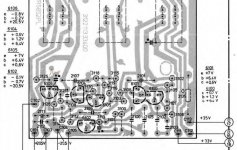
We progress logically by looking at the stage before the one you just tested and that is here. The output of this new stage connects to the input of the stage you just tested. Its the line marked "tweeter/squawker/woofer.
Look at the two transistors marked 6403 and 6404 and the point where the emitters connect together. You can try carefully buzzing that point as we did before with a screwdriver. Also confirm that the connection from the stage with transistor 6106 carries through to the next stage i.e. connection through A425 (is that a plug/socket ?) is good.
You can also jump in and buzz the base of transistor 6106. That's the top of that unreferenced 2.2n capacitor. That switch is worth looking at. Any position will work but if its had a clout it could be open circuit if any print has been broken. So check the continuity (with it all switched OFF) through that switch and resistor network. Between the emitter of 6106 (the emitter is the one with the arrow) and the 560n capacitor marked 2409 on the other board should read either 1k or 5.3k depending on the switch position. (You can read those in circuit because the cap isolates the meter from the circuitry).
If nothing is revealed with these tests then check the DC voltages on the three transistors which should agree with those on the diagram.
Attachments
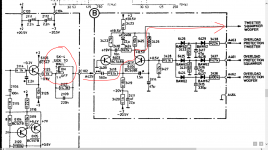
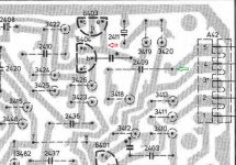
Buzz between 6403 and 6404. No buzz on 6106. See arrow test points marked red (solder points were there to test on).
Continuity between 6106 and 2409, see green arrow test points (5.31k).
Connections on the small neon board are all soldered, none hanging down. I cannot identify A425?
Voltage checks; please be pacific, were doing good!
Chriscam thank you for your advice; it is always welcome, thanks!
Continuity between 6106 and 2409, see green arrow test points (5.31k).
Connections on the small neon board are all soldered, none hanging down. I cannot identify A425?
Voltage checks; please be pacific, were doing good!
Chriscam thank you for your advice; it is always welcome, thanks!
Attachments
Hmm...
Buzz on 6403/6404 is good. We need to find why there is none when you buzz 6106. There could be a problem around that stage or it might just be that the impedance is to low to allow 'buzzing' of that stage.
So voltage checks. Just measure and record the three terminals on 6106. That's C, B and E. There should be 20 volts or so on C (the main supply) and around what is says (-0.2 and -0.8) on the base and emitter.
Are they correct ?
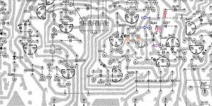
tip : the poweramp can be easily checked by disconnecting the connector below, the red dots are the inputs.
Thanks Chris. I've never actually seen one of these units so am just working off the circuit diagram
- Status
- This old topic is closed. If you want to reopen this topic, contact a moderator using the "Report Post" button.
- Home
- Amplifiers
- Chip Amps
- Philips 22AH587 replica modules