wil the lm need mica isulators even if the heatsink does not touch the casing and there are 2 chips on the heatsink
- Yes it is advisable to fully insulate both LM devices from the heatsink. Their tabs are at -25V and would potentially short this rail to anything the heatsink touches!
![DSCF2885[1].JPG](/community/data/attachments/302/302583-63d003d450c7db534e9e069f52af0c97.jpg)
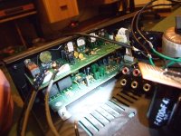
this amp alerardy has an rc4558p up amp preamplifier so it may me too loud,i need to change the preamp chips gain to 1 ,its also +- powered so this is why i needed the the two 15v regulators,also the board has input a and b and a preamplified output coming out of pins marked R and L,
AL and AR are from input a from the back,and BL BR is from input B
LOUT AND ROUT i guess are the output to amplifier,Please tell me what to modify to make that chips gain 1 so there is no amplification since the amp is loud enough at line level
AL and AR are from input a from the back,and BL BR is from input B
LOUT AND ROUT i guess are the output to amplifier,Please tell me what to modify to make that chips gain 1 so there is no amplification since the amp is loud enough at line level
Attachments

Last edited:
If the amp is loud enough - don't bother with preamp! Make input switches (if necessary) and a volume control. Most modern equipment (CD players, Tuners, Computer sound outputs) have enough drive and a preamp is probably not needed!
If you want to change the preamp gain you'll need to supply the schematic for that preamp as I cannot guess from the pictures!!
If you want to change the preamp gain you'll need to supply the schematic for that preamp as I cannot guess from the pictures!!
Last edited:
Nope cant find such thing,i searched for the schematic for 2 yearsIf the amp is loud enough - don't bother with preamp! Make input switches (if necessary) and a volume control. Most modern equipment (CD players, Tuners, Computer sound outputs) have enough drive and a preamp is probably not needed!
If you want to change the preamp gain you'll need to supply the schematic for that preamp as I cannot guess from the pictures!!
no it won't its another car amplifier chip and needs at least 7V.It didnt work ,it wont power on at 5v
the only thing you'll be able to drive reliably off usb is a pair of lm386 for approx 0.5W per channel.... its enough if you have some very efficient speakers and don't want it too loud!!
I aleardy have an tda2003 for usb which im using right now but its mono and my friend also wants one so im going to buy 3 more chipsno it won't its another car amplifier chip and needs at least 7V.
the only thing you'll be able to drive reliably off usb is a pair of lm386 for approx 0.5W per channel.... its enough if you have some very efficient speakers and don't want it too loud!!
yep but i cant find not event a crt monitor thrown out these daysif you can find an old laptop supply 12 to 18V they usually give out several amps and would be ideal!
Authentic TDA2050 ICs turn on at 3 volts. The LM1875 turns on at 9 volts. The TDA2050 has a slightly higher output swing at a given supply voltage than the 1875 and it has 5 amps of peak current vs 4 for when you really push it. It sounds just as good to my ears. The TDA2050 is all around a better chip in my book.
BTW, if you want people to help you, you need to focus on one chipamp and design. Stop bouncing all over the place. Most people have stopped replying to this thread. Too many questions and no focus.
BTW, if you want people to help you, you need to focus on one chipamp and design. Stop bouncing all over the place. Most people have stopped replying to this thread. Too many questions and no focus.
I really agree but I need to find the schematic for the preamp in that amp,im going to take a photo of the bottom of the board and someone coud figure out what schematic it is, or most better i wil do it.Authentic TDA2050 ICs turn on at 3 volts. The LM1875 turns on at 9 volts. The TDA2050 has a slightly higher output swing at a given supply voltage than the 1875 and it has 5 amps of peak current vs 4 for when you really push it. It sounds just as good to my ears. The TDA2050 is all around a better chip in my book.
BTW, if you want people to help you, you need to focus on one chipamp and design. Stop bouncing all over the place. Most people have stopped replying to this thread. Too many questions and no focus.
But that tda 2050 turns on and works at 5 v in single supply?
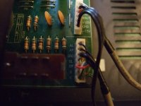
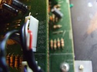
Even more pics of the sittuation on the lm1875
Attachments
![DSCF2896[1].JPG](/community/data/attachments/309/309998-f7f2041a77f35c4005e5ec994e862f91.jpg)
![DSCF2895[1].JPG](/community/data/attachments/309/309991-6924794bde2f423fb910b532d0ab3133.jpg)
![DSCF2894[1].JPG](/community/data/attachments/309/309977-848cd8e6e0b5d4921b4b4850ef0b2787.jpg)
![DSCF2893[1].JPG](/community/data/attachments/309/309967-9c9637bcb9f6006faa25db7bc0d1ca65.jpg)
![DSCF2892[1].JPG](/community/data/attachments/309/309957-68b1317bc1983b282d618bef541f30a8.jpg)
![DSCF2897[1].JPG](/community/data/attachments/310/310005-99ae0b9ca2570ba9da77f3931f22db52.jpg)
Last edited:
I'd say if you ever give up on finding the schematic for that board, google 3 band tone control and rebuild it salvaging (carefully) the pots from that board. There seems to be delay line circuits amongst others involved on that board but without schematic it's almost impossible to tell whats going on....
- Status
- This old topic is closed. If you want to reopen this topic, contact a moderator using the "Report Post" button.
- Home
- Amplifiers
- Chip Amps
- lm1875 fizzing away probelm