Thank you so much for the testing.
In the audio band, the testing shows:
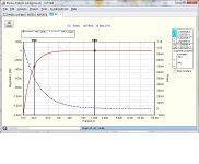
1). Almost flat with 1n
2). Droops inside the audio band with no comp (and a droop at 20khz will damage the harmonics that support 10khz, thus supporting Bob's comment about inferior treble described as "no sparkle").
The "Here is 2.7nF and 1nF" chart shows that 1N+18R or 470p+15R is likely to have a flat response within the audio band. . .
On your board, not everyone's board.
Need of compensation changes with board layout. It is a "moving target" problem. The schematic that you found is for the Jim's Audio TDA7294 single layer mess. However, it is noticeable that the Parallel TDA7293 board doesn't use lead lag comp at all.
Here's a TDA7294 schematic schematic without added comp.
In the audio band, the testing shows:
1). Almost flat with 1n
2). Droops inside the audio band with no comp (and a droop at 20khz will damage the harmonics that support 10khz, thus supporting Bob's comment about inferior treble described as "no sparkle").
The "Here is 2.7nF and 1nF" chart shows that 1N+18R or 470p+15R is likely to have a flat response within the audio band. . .
On your board, not everyone's board.
Need of compensation changes with board layout. It is a "moving target" problem. The schematic that you found is for the Jim's Audio TDA7294 single layer mess. However, it is noticeable that the Parallel TDA7293 board doesn't use lead lag comp at all.
Here's a TDA7294 schematic schematic without added comp.
Attachments
Last edited:
Thank you so much for the testing.
In the audio band, the testing shows:
1). Almost flat with 1n
2). Droops inside the audio band with no comp (and a droop at 20khz will damage the harmonics that support 10khz, thus supporting Bob's comment about inferior treble described as "no sparkle").
You need to spend more time looking at the scale of my drawings.
With no compensation: -0.004dB down at 20Hz, -0.1dB down at 20KHz.
With 15r+1nF = the boost OUTSIDE the audio band will greatly affect the harmonics inside the audio band.
Note: the droop at 20KHz is due to the preamp section inside the AUDIOSOURCE, not due to the TDA7294.
Additionally the overdamped filter created by the "snubber" circuit is yanking quite a bit on the phase, throwing the treble section out of phase by several degrees in BOTH directions (even when using the 15r+1nf).
Perhaps more experiments can be run with a lower resistance factor, but my opinion remains - why in the world would you want to ADD a filter that will only negatively affect the purity of the audio signal? Any filter that gets added cumulatively adds to phase deviations, even if it makes the actual response "flatter".
IMHO, the audio should be as pure as possible. Any "colorations" that make the treble seem brighter or the midrange more muddy is likely due to phase deviations, distortion, or other non-PURE audio signals. Now, that's not to say that one person may or may not like the way those phase deviations sound. SRS makes all of their money by yanking on the phase in the treble region to make things seem brighter. Some people like this. That's why SRS stays in business. I personally find phase deviations to be fatiguing over time, and I turn off any SRS, Dolby, DTS, or Beats processing that I find on any of my systems.
What is your source impedance and how does this affect the measurements? Is response okay if the volume pot is removed?
I was wondering why a chipamp like this would need any kind of external compensation when it is supposed to already be stable.
Since Dan thought the chip was unstable, I gave him instructions on how to apply this kind of compensation. I was worried he would have trouble without a scope but he was willing to try it out. I wonder how much of its effect comes as an EQ control and how much comes from an effect on stability or RFI tolerance.
Keane,
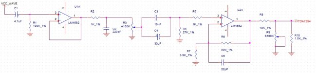
To answer your question, I quickly drew up what the preamp section of this HEAVILY modified AudioSource amp looks like.
The topology of the factory amp is the same, but I've heavily modified the values to achieve a much flatter response than normal.
The droop you see in my non-compensated response is actually due to two different things:
1. The R2/C2 combination
2. The C5 value through the U2 op-amp
These values are what is currently populated and being measured. I have no idea why audiosocure wanted to boost the output about +14dB through the op-amp, then immediately yank it back down to 0dB with R10, but they did.
Anyways, I hope this helps. The TDA7294 appears to be waaaay more than stable (at least in this design).
Attachments
So output impedance is at most 1.5k. With such a large RC across the inputs, input impedance can be changed enough to cause problems with reasonable source impedances. I'm not sure how much that applies in this case.
You may think about trying to lower the source impedance. With many poweramps a large source impedance will bring out more distortion.
You may think about trying to lower the source impedance. With many poweramps a large source impedance will bring out more distortion.
Absolutely true and totally expected--Compensation needs can change with board layout.Clearly lead-lag compensation is a bad idea in this case. Thanks for measuring and posting")
Much earlier, I had mentioned that the lead lag comp was put on because of one specific board with bad layout; specifically it was the Jim's Audio single layer TDA7294 board which behaved so badly I thought the chip was fake. Yes, that board has a rather annoying influence--Removing the board also removes the problems.
Testing results seem to indicate:
I need to retry the Jim's Audio Single Layer TDA7294 Board, remove the lead lag effect, and then try to work out the rest with power circuit mods for correcting the layout issues. Maybe a full scale implementation of Tom's and KSTR's iteration array daughtercards could help remove/dampen the sonic weapon coloration of that one particular board layout--the Jim's Audio single layer TDA7294 that needs either a timely disposal or much more help.
Compare:
There's no lead lag comp used on the TDA7293 Parallel board. Likewise, the AudioSource AMP-100 board doesn't need lead lag comp. Apparently, those two amplifier boards have a useful layout.
There is one more case, where I'd expect to see exactly the treble droop shown, and that case is: If the "1u or 0.47u electrolytic" bypass cap were omitted (at the nfb-shunt cap area), then I'd expect a small treble droop. I'd suggest to test drive some bypass caps to see if you get a flatter response and clearer sound. If your large size NFB-shunt cap is of most excellent quality then adding the "1u or 0.47u electrolytic" might be overkill, in which case a little green polyster dip cap with values such as 22n or 10n or smaller may do.tyger23 said:The droop you see in my non-compensated response is actually due to two different things:
1. The R2/C2 combination
2. The C5 value through the U2 op-amp
Yes, I like cool and efficient. Thank you so much for checking the stability and amplifier behavior!tyger23 said:Anyways, I hope this helps. The TDA7294 appears to be waaaay more than stable (at least in this design).
SO, my question is, once the comp (that your board didn't need) was removed, then did you find the rest of the design suitable? And, what changes, if any, would you suggest?
Last edited:
The LM4562 has a closed-loop impedance of 0.01 ohms. I don't think I can lower it much past that.
Look at your own schematic. It has a 10k resistor in series with the output, only mitigated by the 1.5k shunt resistor!
SO, my question is, once the comp (that your board didn't need) was removed, then did you find the rest of the design suitable? And, what changes, if any, would you suggest?
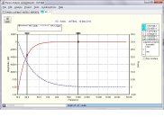
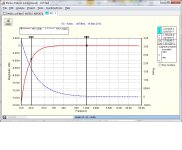
The one suggestion I would recommend is to change that input cap. You currently show a 1uF with a 27K resistor. If you check out the bode plot for this filter, you'll see that it will cause a 0.35dB droop at 20Hz (which isn't too bad), but the bad part is that you're 17 degrees out of phase.
I would recommend 22uF or greater. I personally use a 33uF when there's a 27K input impedance. Attached are the simulations for a 1uF, 10uF, and 33uF input cap. Alternatively, I guess you could change the input impedance. Enjoy!
Attachments
Thanks!
I can probably manage 10u||10n with the Parallel TDA7293 board or any of the little compact double-layer boards by same designer, or point to point, or really any excellent layout is also compatible with using a larger input cap. I already tried 5.5u with the TDA7293 Parallel board, and it was just fine.
Input load:
I'm curious about this. The valid range for input load seems to be 12k through 27k. Smaller figures do louder midrange and a few other things as well. There's no problem to use a 22k or 18k input load. Would that help?
Last edited:
There's no problem to use a 22k or 18k input load. Would that help?
Lower input loads would make the droop and phase issues worse.
FWIW - I would also recommend Nichicon KZ or FG caps for the inputs. Also, the Elna Silmic II caps are just as good if not better. There's no real need for a bi-polar cap on the input pin.
Lower input loads would make the droop and phase issues worse.
FWIW - I would also recommend Nichicon KZ or FG caps for the inputs. Also, the Elna Silmic II caps are just as good if not better. There's no real need for a bi-polar cap on the input pin.
Okay.
I'm willing to do larger size input caps, but only in case of good board layout which is the minority--the compact dual-layer boards listed in post#455, and also point to point (compact triple-layer). Perhaps these have the power caps located close enough to pins 7 and 8 that we have more freedom in fine tuning the amplifier. That's a guess, but I know for sure they're easier to work with for achieving an appreciable practical output. And, your big input caps will do just fine with those decent boards. . . which are the minority.
For the majority, 1u input cap is a safe bet to show on the schematic because the majority are the "inductive spaghetti" single layer boards that have the power caps too far away from the chip with annoying results that get worse if the input cap is made larger. Bad layout boards are the majority, which is what happens when sprawling single layer board design meets a chip with mad pinout. It is possible to make plug-in daughtercards for bypassing problem areas of bad boards; however, a thorough job of it bypasses every circuit and thus it would be so much easier to replace a bad board instead of fight with it.
Anyway, it is really a problem to show board specific values on any schematic that doesn't also show layout.
Last edited:
I'm not repeating a whole post, since the original is here: TDA7293 Parallel Thread
But there was a pertinent photo that I'd like to share since I did first try it on Bob's TDA7294 board:
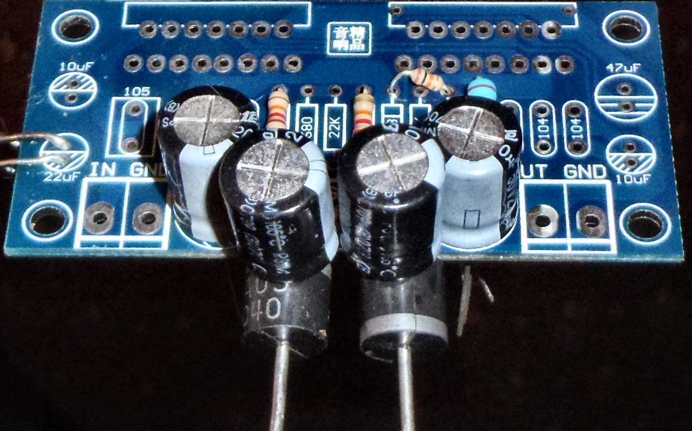
On Bob's single layer TDA7294 board, a power circuit mod very similar to what is shown in the photos (same component values) did cut the need of compensation in half. Note: The TDA7293 Parallel amp board in the photo has V+ on the left side (your board might be different, so double-check). These parts and the 440u per rail are shown on this schematic. Powered like shown in the photo above, it will be much easier to fine tune the amp.
The feedback-shunt trimmer for adjustable gain goes a long way towards not needing added compensation at all. In addition to unimportantly setting the gain, it also varies the tone, mainly treble versus bass, which is expected because of changing the gain, so please use the trimmer to dial in a level response precisely. That's good but a midrange control was previously missing. To fix that, I've added adjustable input load to the schematic.
Functions:
Gain trimmer = Treble versus Bass (dial it in for level)
Input load trimmer = Midrange soft or loud
Notes:
You can replace the 100k input load trimmer with an equivalent resistor after you've completed your fine tuning; but, that is not true of the 100R gain trimmer--it needs to stay on the board. If your board has a fortunate layout for good behavior, then you'd be able to use an input cap larger than 1u, if desired.
But there was a pertinent photo that I'd like to share since I did first try it on Bob's TDA7294 board:
On Bob's single layer TDA7294 board, a power circuit mod very similar to what is shown in the photos (same component values) did cut the need of compensation in half. Note: The TDA7293 Parallel amp board in the photo has V+ on the left side (your board might be different, so double-check). These parts and the 440u per rail are shown on this schematic. Powered like shown in the photo above, it will be much easier to fine tune the amp.
The feedback-shunt trimmer for adjustable gain goes a long way towards not needing added compensation at all. In addition to unimportantly setting the gain, it also varies the tone, mainly treble versus bass, which is expected because of changing the gain, so please use the trimmer to dial in a level response precisely. That's good but a midrange control was previously missing. To fix that, I've added adjustable input load to the schematic.
Functions:
Gain trimmer = Treble versus Bass (dial it in for level)
Input load trimmer = Midrange soft or loud
Notes:
You can replace the 100k input load trimmer with an equivalent resistor after you've completed your fine tuning; but, that is not true of the 100R gain trimmer--it needs to stay on the board. If your board has a fortunate layout for good behavior, then you'd be able to use an input cap larger than 1u, if desired.
Attachments
Last edited:
in this case also this thread is of interest:
http://www.diyaudio.com/forums/chip...ons-tda7293-tda7294-lm3886-etc-available.html
http://www.diyaudio.com/forums/chip...ons-tda7293-tda7294-lm3886-etc-available.html
And, here is a shortlist of efficient dual-layer boards:
TDA7294 solo: TDA7294 Mono Amplifier Kit
TDA7293 solo: TDA7293 Mono Amplifier Kit
TDA7293 Parallel: Parallel TDA7293 Mono Amplifier Kit
TDA7293 Triple: Triple Parallel TDA7293 Mono Amplifier Kit
*See also this mods list with photos and assembly.
P.S. Honorable mention:
http://www.diyaudio.com/forums/class-d/231988-what-heck-its-less-than-lunch.html
Last edited:
And, here is a shortlist of efficient dual-layer boards:
TDA7294 solo: TDA7294 Mono Amplifier Kit
TDA7293 solo: TDA7293 Mono Amplifier Kit
TDA7293 Parallel: Parallel TDA7293 Mono Amplifier Kit
TDA7293 Triple: Triple Parallel TDA7293 Mono Amplifier Kit
*See also this mods list with photos and assembly.
P.S. Honorable mention:
http://www.diyaudio.com/forums/class-d/231988-what-heck-its-less-than-lunch.html
I have just purchased a pair of TDA7294 finished boards for $11.4 and they arrived in under 2 weeks!
No stand offs, I guess the image is generic, but they came with mica and plastic insulators.
I think I can manage to cobble together a PS, I have several SS amps I will never use.
Amplifier PCB board TDA7294 Amplifier board(1+1) Dual channel 2*85W-in Printer Parts from Office & School Supplies on Aliexpress.com
Let us know when you get it hooked up. I'm getting too many TDA* based amps around here myself - with too little time to work on them.I have just purchased a pair of TDA7294 finished boards for $11.4 and they arrived in under 2 weeks!
No stand offs, I guess the image is generic, but they came with mica and plastic insulators.
I think I can manage to cobble together a PS, I have several SS amps I will never use.
Amplifier PCB board TDA7294 Amplifier board(1+1) Dual channel 2*85W-in Printer Parts from Office & School Supplies on Aliexpress.com
Plus a move to CT coming up this Summer. Might grab a couple of these for fun!I have just purchased a pair of TDA7294 finished boards for $11.4 and they arrived in under 2 weeks!
No stand offs, I guess the image is generic, but they came with mica and plastic insulators.
I think I can manage to cobble together a PS, I have several SS amps I will never use.
Amplifier PCB board TDA7294 Amplifier board(1+1) Dual channel 2*85W-in Printer Parts from Office & School Supplies on Aliexpress.com
Lucky, I ordered two of the 2 chip kits and got .... one 2 chip kit and one 3 chip kit!?!
Hopefully it'll resolve quickly so I can give Dan's circuits a try ...
And, here is a shortlist of efficient dual-layer boards:
TDA7294 solo: TDA7294 Mono Amplifier Kit
TDA7293 solo: TDA7293 Mono Amplifier Kit
TDA7293 Parallel: Parallel TDA7293 Mono Amplifier Kit
TDA7293 Triple: Triple Parallel TDA7293 Mono Amplifier Kit
*See also this mods list with photos and assembly.
P.S. Honorable mention:
http://www.diyaudio.com/forums/class-d/231988-what-heck-its-less-than-lunch.html
Daniel,
Thanks you the info! I came upon this thread by accident and your posts stoke my interest on these TDA792X chips. I was planning to try out the LM3886/3875 chips but these TDA seems to be much more economical to play with. I hope they sound "as good" as the LM chips.
I probably will build the amp as-is, and then mod it according to your and others suggestions, as a learmning process.
Regards,
- Status
- This old topic is closed. If you want to reopen this topic, contact a moderator using the "Report Post" button.
- Home
- Amplifiers
- Chip Amps
- Optimizing TDA7294 Output