Since large capacitor discharge blowing out the small signal section is unsafe, the resulting capacitor value is: DC TrackerAt 1K,22k,what value will be for cap?
000u with 680R and this isn't a good
idea because it is hard to find small
signal worthy 1000u caps and that
much cap discharge can break the
input transistors.
What do you mean,,can u plz xplain a bit,Why not 220,470u with 680R ?1000u with 680R and this isn't a good
idea because it is hard to find small
signal worthy 1000u caps and that
much cap discharge can break the
input transistors.
That will work with LM3886. The undersize NFB cap will cause some 2nd order harmonic distortion at the bass and warm up the sound.What do you mean,,can u plz xplain a bit,Why not 220u or 470u with 680R ?
However. . .
TDA7294 doesn't have an inbuilt hard clipper. Nope. So, we don't have any sort of spike system mids&treble noise to combat. Instead of sudden onset, TDA7294's softie limiter doesn't make mids&treble distortion. No free lunch--Unfortunately, the only means to do softer limiting is earlier engagement. Basically, instead of upper midrange distortion like NatSemi's LM3886. . . ST's TDA7294 omits the low bass. Big difference! Omitting the low bass during loud playback is a highly effective means of current management for safety but it also causes "warm sound" artifacts, such as muddy sound.
Unfortunately, this also affects dynamics.
Actually, both NatSemi's hard clipper and ST's softie limiter do affect dynamics. Both are providing a necessary safety function, but neither is fun.
Well, that's a mess. Let's just say the dynamic tone is different. Thus the audiometric tuning needs are different.
TDA7294 is already warm enough, that is distortion, especially on dynamics and louder playback, and we don't want to make it worse.
SO, to get good low bass out of ST's TDA7294, we have to prepare with a larger NFB cap, a larger bootstrap cap, larger power supply reservoir and a larger transformer. And we don't dare try for much "warm up" with TDA7294 because that would do nothing but mid-fi mud, and as you can tell by that, undersize NFB cap is a mistake we'd like to avoid.
Also, to avoid excess "warming" (mud) with TDA7294, we don't put super-large caps on the amplifier board (much different than with LM3886). However, if you did happen to want larger capacitance on a TDA7294 amplifier board, you could use several 220u (or smaller) in parallel per each rail as the small cap still sounds clean even if you gang up several of them. I don't know why.
Most of ST TDA7294's softie limiter system is thermally reactive, so in order to keep the "mud slinging" to a minimum we must make tweaky tuning choices based on heatsink temperature--Consider anything that causes more heat a "veto." Before starting any tweaky tuning, an excellent head start would be clean power so the chip can run cooler. That's why I've been rather persistent with the power circuit on this thread. When the chip runs cooler, the resolution is a LOT higher.
P.S.
A much shorter answer to your question is: Bass blocker/distorter, and we don't need that extra distortion.
Undersize NFB cap error can make the cap selection extremely difficult to do, because it is the wrong size and thus finding a suitable brand of audiophile capacitor (of the wrong size) could be quite frustrating and time consuming.
P.P.S.
Easiest fix for undersize NFB cap is to decrease the +input cap size (input filter roll-off at least an octave higher frequencies than the feedback-shunt RC). This is quite the useful consideration for rear channel amp and mids&treble amplifiers for bi-amp system. Small, small value +input caps for clean sound.
Last edited:
He's Back ")
Sorry, been playing in the discrete amp sandbox for my three design challenge project. (if interested check here)
I needed a method to start the component swap testing so I built a open bottom brace. I'll use that in combination with sockets when I start the comparison process. Will be adding some alternative parts in the next online orders.
Also got a start on a PS by mixing some new and some on-hand components. Between emails and posts, Daniel has me thoroughly confused so I'll just post what I have and ya'll can set me straight.
Sorry, been playing in the discrete amp sandbox for my three design challenge project. (if interested check here)
I needed a method to start the component swap testing so I built a open bottom brace. I'll use that in combination with sockets when I start the comparison process. Will be adding some alternative parts in the next online orders.
Also got a start on a PS by mixing some new and some on-hand components. Between emails and posts, Daniel has me thoroughly confused
so I'll just post what I have and ya'll can set me straight.Attachments
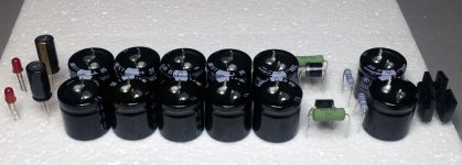
Bob, most of those parts look good.
However, I see a 3 divergences that don't match the schematic. . .
1). No need to cause ringing with the unexpected extra 100u caps (omit for now).
2). If your transformer is dual-secondaries, the bass could be better if you use dual-secondaries specific support. See photos (attached).
3). Capacitor polarity needs checked. See photos (attached).
Attachments
We need to talk about "Derating."
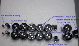
Bob, in regards to that one mystery 35v cap on the rails in your picture:
The 35v rated cap on 35v rails is like setting the cruise control on a Chevy Corsica stuck at maximum speed, 143 miles per hour, which would shorten longevity dramatically. Likewise, the 35v rated cap running on 35v rails won't last long.
Derating for longer lasting:
50v rated caps, 35v rails, TDA7294, 24+24vac transformer
63v rated caps, 48v rails, HoneyBadger, 35+35vac transformer
The deal is that getting any practical long-term use out of anything either electronic or automotive requires it be used at somewhat less than floorboarded. Unfortunately, the sensational headlines of marketing figures (like the voltage printed on the side of caps) don't usually include longevity, and datasheets are advertisements, especially the first page with the headline/destructive test, peak rated figures that aren't for practical use.
Some approximate examples:
An active device may run up to 40% of its rating at conservative voltage or up to 20% of its rating at higher voltage.
A passive part may run up to 60% of its rating at room temperatures or up to 35% of its rating at warmer temperatures.
Those generalizations are somewhat imprecise, but none of them run at 100% of their advertisements. Therefore, the voltage figure printed on the side of the capacitor is not really trustworthy--it is a "headline figure" aka marketing BS. The fix for this problem is Derating.
Last edited:
Hey Daniel,
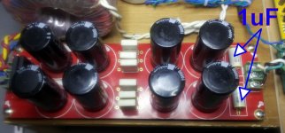
There may just be a computer graphics problem here. I used the drawing attached to post # 78 as my key. I saw uF and on closer examination that may nF - not sure.
But I'm glad you caught it. That's why I posted what I have before heating up the soldering iron. Also the red PS in the same post has a cap in a similar spot, so some more clarification may be needed. Are you suggesting that specific cap be completely eliminated, replaced with a different value or it's something for center tapped transformers only?
There may just be a computer graphics problem here. I used the drawing attached to post # 78 as my key. I saw uF and on closer examination that may nF - not sure.
But I'm glad you caught it. That's why I posted what I have before heating up the soldering iron.
Also the red PS in the same post has a cap in a similar spot, so some more clarification may be needed. Are you suggesting that specific cap be completely eliminated, replaced with a different value or it's something for center tapped transformers only?Attachments
Yes, that 100n can be eliminated. Let's call it "TBD" (to be determined) status. You may want something as small as 22n polyester dip (not box) cap, or as large as 2u electrolytic. . . or no extras at all. There's no telling until after an audio amplifier is connected.But I'm glad you caught it. That's why I posted what I have before heating up the soldering iron.
The wrong cap can really put a dreadful kink in the treble, but omission does not have that risk. For sure you'll want to try the power supply, first, without that extra cap.
I think that I found out where the 100n came from.. . .something for center tapped transformers only?
On a center tap CRC power supply, the smoothing section at the bridge rectifier has its own ground. . . and then effectively a heavy duty jumper. . . to the reservoir/tank section that has a massive star ground. . . and then another heavy duty jumper. . . to the output jack. Aha! That last bit could have some little 100n caps or something at the output jack.
Well, the main point of this post is showing that a Center Tap specific CRC power supply has a different and somewhat more complex grounding scheme. Suitability for multi-parallel little caps power supply was limited, but I think I've managed to draw it.
Attachments
Last edited:
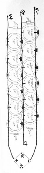
Looks like the PS boards I have been using will accommodate both styles of transformers. They have the small caps installed but work just fine with duals I have.
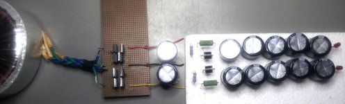
Since we didn't have "show and tell" when I was in school I'll try to make up for lost time here This is a little mock-up for final approval. Of course I'll use bigger wire (or copper strips if advised so) for the final construction. I have never done a DIY etched PCB so that might be another new adventure.
Since we didn't have "show and tell" when I was in school I'll try to make up for lost time here
This is a little mock-up for final approval. Of course I'll use bigger wire (or copper strips if advised so) for the final construction. I have never done a DIY etched PCB so that might be another new adventure.Attachments
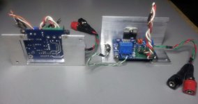
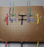
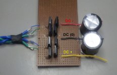
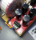
Right side picture, you have a dual secondaries transformer and it can perform more strongly when given specific support. That's good news.
You have two secondary windings--use ohmmeter to identify secondary#1 and secondary#2. And separate the output cable of your transformer so that you have a twisted pair of conductors for secondary#1 and a separate pair of twisted conductors for secondary#2.
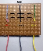
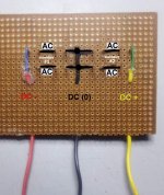
Middle picture, don't attach any cable from a dual secondaries transformer to any part of the DC rails. All AC must go through the diodes (per every dual secondaries type schematic). See attachment.
You have two secondary windings--use ohmmeter to identify secondary#1 and secondary#2. And separate the output cable of your transformer so that you have a twisted pair of conductors for secondary#1 and a separate pair of twisted conductors for secondary#2.
Middle picture, don't attach any cable from a dual secondaries transformer to any part of the DC rails. All AC must go through the diodes (per every dual secondaries type schematic). See attachment.
Attachments
Center tap vs dual secondaries? The deal is that those two styles are competitors, like Windows VS Mac.
Without hindering bass/dynamics from dual secondaries transformers and without setting center tap transformers ablaze, a solution with neither problem has both hookups. I've never seen one because it would make more sense to put the bridge rectifier(s) on "daughtercards" and plug in whichever you needed.
However. . . Like a Jeep or Scout than can do either car or truck, here (attached) is a hermaphroditic power supply board that can use either a center tap or a dual secondaries transformer, properly. Proposed use: A "Tester" power supply for bench use.
Attachments
Hey Daniel,
It's a good thing I don't embarrass easily. Here is the latest. Am I getting close?
Again, some of my confusion comes from my existing board . It is using the "3 point" configuration with dual secondaries. I believe you are saying that will work but is not optimal for this particular application. Is that correct?
It's a good thing I don't embarrass easily.
Here is the latest. Am I getting close?Again, some of my confusion comes from my existing board . It is using the "3 point" configuration with dual secondaries. I believe you are saying that will work but is not optimal for this particular application. Is that correct?
Attachments
It is not optimal for your transformer--Using center tap power board with dual secondaries transformer causes "poorer regulation" and what that does is make the transformer act like it has less VA, so then the bass and dynamics falter due to early onset of transformer throttling. See also post#274Again, some of my confusion comes from my existing board . It is using the "3 point" configuration with dual secondaries. I believe you are saying that will work but is not optimal for this particular application. Is that correct?
Oh yes, the latest photos of the handmade stuff looks correct.Here is the latest. Am I getting close?
Well, what I use is 12ga or 14ga Romex, solid copper. I have to sand the coating off first. And then the wire is so darned thick that it is difficult to solder and takes a rather strong soldering iron.Thanks, what are your recommendations for the main buses? I've seen big wires, plates, strips of copper and of course PCBs (perfboards).
- Status
- This old topic is closed. If you want to reopen this topic, contact a moderator using the "Report Post" button.
- Home
- Amplifiers
- Chip Amps
- Optimizing TDA7294 Output