I have not recommended any zener for this amplifier, as is evident by my published schematics.
In fact, I have simplified the matter so that you don't have either the breakage or the zener.
I have a slightly bulky cap array arrangement for that task, but I have not recommended a DC servo as is evident by my published schematics.
Very irritated! It is not recommended to install additional distortion.
I sure do understand that part of your comment. Yes, the TDA7293 can get readily informative about its needs. It will be convenient if you don't install mixed advices from the whole of the internet into just one amplifier.
And, in fact, if you're not making mine, then your adventure needs a thread of its own.
Even though that need is likely, also I understand, and also you are plenty welcome to post anything about a TDA7293 on this thread.
But, as for mine, please attempt to build it on spec and report back after having done so.
Well, I'm alarmed and I'm trying not to complain too much; but, it is very difficult to help you if you make a random thing without an expected function.
I'm sorry, I thought you knew I was reffering to the TA2022 about the DC-offset etc.
I wrote that as a sidenote to compare it to the TDA7293 kits that are on the way. Those btw are the same as in the first post in this thread, that post was made by you.
You then offered advice etc on the issue, I figured you where aware that I was writing about the TA2022 boards, and I answered assuming that.
As for the mods to the TDA7293 kits, those are mainly suggested by you, in this thread.
In fact, the only info applied, well to be applied, to the TDA7293 kits is taken from this thread as it is the one I've read (so far atleast).
The other info I reference is for the TA2022, again I brought that up as an interesting sidenote that I would compare it to the TDA7293 in parallel.
I hope that clears things up a bit.
I "got done" with the amp today.
I've only had time to measure supply voltages and Dc-offset. The latter is very low except for when switching off the amp. It then rises to >1.5Vdc before quickly dropping to around 400mV where it sits.
This is with empty, un-shorted inputs and no load.
Is the DC offset normal under these conditions?
I did build the amp with all modifications suggested.
What is the offset if the amplifier output is given a resistive load of about 6 ohms?
The offset voltage may change when loaded.
The input does short when you turn off the amp--that's what the mute switch does.
Seems like you might be describing a "turn off thump" so, I'm curious how much voltage that thump gets while the amplifier does have a load.
The little turn-off thump may be my fault. Since the standby and mute are "stuff to use while not playing audio" I have adjusted the circuit's component values for enhanced safety and sound quality, with little to no regard for their other functions (such as thump suppression). My sample does make a rather quiet, momentary thump after it is shut off. That force pales in comparison to what it had been doing to the speaker while playing music. So, for my sample, the turn off thump was insignificant. There is that matter of why racing bicycles don't have kickstands (stuff to use while stopped).") I didn't work very hard on that part.
I didn't work very hard on that part.
The offset voltage may change when loaded.
The input does short when you turn off the amp--that's what the mute switch does.
Seems like you might be describing a "turn off thump" so, I'm curious how much voltage that thump gets while the amplifier does have a load.
The little turn-off thump may be my fault. Since the standby and mute are "stuff to use while not playing audio" I have adjusted the circuit's component values for enhanced safety and sound quality, with little to no regard for their other functions (such as thump suppression). My sample does make a rather quiet, momentary thump after it is shut off. That force pales in comparison to what it had been doing to the speaker while playing music. So, for my sample, the turn off thump was insignificant. There is that matter of why racing bicycles don't have kickstands (stuff to use while stopped).
I didn't work very hard on that part.
Last edited:
You asked about a Class D amplifier and I DO have a Class D thread. It is an inexpensive TDA8932 chip with a deluxe 5x 100uF power circuit on the board. Unfortunately, in stock condition, it is in bridge mode, which hinders its resolution down to unimpressive. However, there are ready and not completely inconvenient means to use it in SE mode (for tweeter amp) and Mixed mode (for bi-amp).
The relevant difference is mainly room size.
That is much different.
The relevant difference is mainly room size.
That is much different.
What is the offset if the amplifier output is given a resistive load of about 6 ohms?
The offset voltage may change when loaded.
The input does short when you turn off the amp--that's what the mute switch does.
Seems like you might be describing a "turn off thump" so, I'm curious how much voltage that thump gets while the amplifier does have a load.
The little turn-off thump may be my fault. Since the standby and mute are "stuff to use while not playing audio" I have adjusted the circuit's component values for enhanced safety and sound quality, with little to no regard for their other functions (such as thump suppression). My sample does make a rather quiet, momentary thump after it is shut off. That force pales in comparison to what it had been doing to the speaker while playing music. So, for my sample, the turn off thump was insignificant. There is that matter of why racing bicycles don't have kickstands (stuff to use while stopped).
Hi,
I'm still waiting for a pair of 8R/100W resistors to use as dummy loads.
I ordered them a while back, though this time of the year everything takes longer to arrive.
I wouldn't mind a small thump, but I don't wish to test the theory on my 15" Dayton IB's
They cost a pretty penny in shipping across the pond.I'll attach the dummy loads to a heatsink when they arrive and measure the amp when under load.
I am actually looking at that. I have a bunch of 12V relays and the parts (2N7000 etc) to drive it.
I'd be looking for an easy circuit in this case though as I recently did the EV-board relay driver DC-servo circuit(TA2022) on perf board. I used as much 0805's I could to fit it on a 6*8cm board.
It looks messy tbh and eventhough you'll never see it once an enclosure, it's one of those things that bothers me.
A simple circuit that gives about 3-5sec delay on power up and turns the relay off as soon as you switch the amp off would be great.
Sorry about the messy post, I can't find the english words for what I try to say as easily. My 3month daughter is has my brain a little bit "all over the place". She's easy going etc, but being my first child, it's alot to keep track off.
My apologies that I didn't pay attention to turn off thump issues. My test speaker has the Dayton Classic 6.5 and the turn off thump of my sample was SO MUCH LESS than what workload it had been doing while on and playing music that I had disregarded the wee little turn off thump (that couldn't possibly overwork the speaker).
On that note, I do have a racing bicycle, and it doesn't have a luggage rack, basket, fenders or a kickstand, because stuff to use while off isn't something I'd consider relevant while on (and not worth compromised functionality). Well, that's just how it went.
On that note, I do have a racing bicycle, and it doesn't have a luggage rack, basket, fenders or a kickstand, because stuff to use while off isn't something I'd consider relevant while on (and not worth compromised functionality). Well, that's just how it went.
My apologies that I didn't pay attention to turn off thump issues. My test speaker has the Dayton Classic 6.5 and the turn off thump of my sample was SO MUCH LESS than what workload it had been doing while on and playing music that I had disregarded the wee little turn off thump (that couldn't possibly overwork the speaker).
On that note, I do have a racing bicycle, and it doesn't have a luggage rack, basket, fenders or a kickstand, because stuff to use while off isn't something I'd consider relevant while on (and not worth compromised functionality). Well, that's just how it went.
I don't think me, or anyone else, is blaming you for anything.
I was simply stating the results from my own build/measurements.
The DC-offset in my case is high enough(unloaded) that I would not want to hook the amp up in my system before testing it with resistors as loads.
Possibly from there build a relay-circuit depending on my findings with the dummyloads.
The DC-offset, in my case, was climbing to >1.5Vdc before declining to around 500mV where it sits. Now that is without any load on the outputs.
A simple relay circuit that delays signal to spkr and disconnects spkr output instantly at power off shouldn't be that unreliable?
A simple relay circuit that delays signal to spkr and disconnects spkr output instantly at power off shouldn't be that unreliable?
I would not want to hook the amp up in my system before testing it with resistors as loads.
Good plan!
I was thinking that if the current (of the error) is low, then the voltage will drop considerably, if it has a load.
Four ordinary 1/4 resistors of 20 ohm or 22 ohm, used paralleled, would give you an approximate speaker load 5 ohms or 5.5 ohms and a "dummy load" with 1 watt capacity.
So, if that didn't blow up, then you can assume it may be safe to connect a speaker with 1 watt or greater capacity.
I've got a few 555's, 2N7000, 12V (and I think 24V) relays, a lot of zeners etc etc.
I also have a headphone protection board(never used) that uses the UPC1237.
I know, or atleast think, the above can't be used without some modifications/total rebuild.
After some hours searching the net after a simple, reliable design that fits my needs, I came up empty.
I've never worked with the 555 timers, or any timers for that matter.
Any and all suggestions would be grately appreciated.
I feel it would be "better" to use a turn on delay, turn off spkr disconnect, maybe DC sensing regardless of what I measure once the 100W dummy loads I ordered before x-mas arrive.
Attachments
This is the time to put range 4400uF~6600uF (sizing is moderate or larger speaker) in series to speaker negative (suited to our split rail amplifier), to block DC, and then, afterwards, find out if the amplifier works. . . without that inconvenience of dc errata bother.
It is possible that the chips is broken or a build error; however, protecting the speaker from DC is a straightforward matter, quite recommendable during experimentation, and easily done.
This does tend to happen with chip amplifiers. I usually employ 3x2200uF (paralleling) to make the DC filter. Sure it ought to be unnecessary; however, the occurrence of the need, is approximately half as often as using chip amplifiers.
Yeah, that's a band-aid patch, but it sure will block worse errors. I suggest to use it during discovery, while finding out how to do a bit better than that, your speaker still intact.
There are other reasons to use that sort of filter, such as workshop and goodly bass management. Actually, I do like the bass when the filter is exactly at speaker capacity.
I have actually used it in cases that weren't necessary. Well, sometimes, I do crank it up, and that is pleasing when it is appropriate.
So, my actual need of this has nothing to do with test conditions; however, conveniently, the speakers don't ever get harmed.
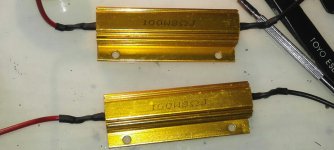
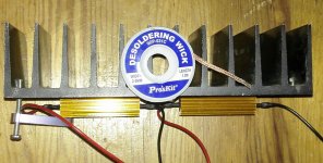
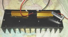
Got the dummy loads mounted on a heatsink today, and got very different readings when measuring DC-offset compared to what I got with unloaded outputs.
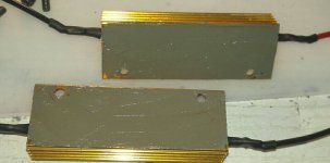
First, I used Arctic Silver 5 TIM between the resistors and the heatsink.
It's a very good TIM, but I use better for my watercooled PC (custom loop and highly overclocked CPU and GPU).
One of the M3 screws I used to mount the resistors to the heatsink broke off(apparently an aluminium screw...) that is why there's a bracket holding one end of one resistor to the heatsink.
I didn't use the heatsink I had intended, when going to drill and tap the heatsinks, I found this old one and thought I'd use it as a permanent heatsink for those dummy loads.
I filmed the power on and power off for both channels, I did the left channel first so, that may read differently than the right channel. I haven't watched the films, I just put them on youtube from my phone. For some reason they are in "flipped" widescreen mode...
Anyway, Left channel:
Left channel
Right channel:
Right channel
So, the numbers measured with dummy loads look alot better, to me atleast.
What do you guys think?
Attachments
Output offset is measured with the input shorted and the output open.Got the dummy loads mounted on a heatsink today, and got very different readings when measuring DC-offset compared to what I got with unloaded outputs.................
You don't connect a dummy load to check offset.
- Home
- Amplifiers
- Chip Amps
- TDA7293 Parallel kit from ebay (modular/slave style, no lossy emitter resistors)