
Got the dummy loads mounted on a heatsink today, and got very different readings when measuring DC-offset compared to what I got with unloaded outputs.
First, I used Arctic Silver 5 TIM between the resistors and the heatsink.
It's a very good TIM, but I use better for my watercooled PC (custom loop and highly overclocked CPU and GPU).
One of the M3 screws I used to mount the resistors to the heatsink broke off(apparently an aluminium screw...) that is why there's a bracket holding one end of one resistor to the heatsink.
I didn't use the heatsink I had intended, when going to drill and tap the heatsinks, I found this old one and thought I'd use it as a permanent heatsink for those dummy loads.
I filmed the power on and power off for both channels, I did the left channel first so, that may read differently than the right channel. I haven't watched the films, I just put them on youtube from my phone. For some reason they are in "flipped" widescreen mode...
Anyway, Left channel:
Left channel
Right channel:
Right channel
So, the numbers measured with dummy loads look alot better, to me atleast.
What do you guys think?
With those readings, you're going to hear a "ka-thunk-a" at no louder than a normal speaking voice and at far less force than the capacity of a speaker that could handle this amplifier's music output.
Well, the voltmeter has shown a turn-off thump at ~1/20th of the required speaker capacity.
That could fry a speaker that is more than 20 times unsuitable for an amplifier with this much output power.
A little 3" full range might x-max to bang the coils. Do use a bigger speaker than that.
The amp is to power one 15" Dayton IB/channel.
You can try the board's default/marked arrangement for the mute circuit, to see if you get a different amp turn-off behavior.
So the ON/OFF "thump" would be to high for my Dayton 15" IB woofers?
I do have a spkr protection board that is currently in another amp....
Oh, no, that thump is not too much for any speaker that could withstand this amp used full blast. Mine says a wee little ka-thunka (through the speakers) and not very loud. Well, at least I suppose it wasn't very loud because, just before that I had the music actually very loud. 
I was thinking that it is worth an experiment to try re-timing the standby and mute circuits to see if that has any verifable merit. I would like you to try the board vendor's mute circuit idea to see if it resolves the thunks.
It would be a great favor to me if you'd compare the thonks of my circuit with the board manufacturer's suggested mute circuit (conveniently already laid out on the board).
For reference:
My Dayton 6.5" woofers haven't been harmed in nearly a decade by the absence of the mute cap, although the resolution of my Pioneer 2" paper tweeter would be ever so slightly harmed by the presence of the mute cap. With the mute cap in place, my choices are to either suffer the baleful tone of slightly less stability (that heat also means less output power capacity) or dial up the gain to maintain the goodly tone at the cost of less tweeter resolution (and, in my case, there was none to spare). So, that's why I pulled the cap. Alternatively, it was possible that it is a layout issue (quite probable considering the mad pinout).
Summary:
Investigate the power off thonks difference between my schematic's mute circuit and the board manufacturer's mute circuit suggestions.
Consider bi-amp as the fast track to hi-fi, because the needs of the woofer and the tweeter conflict a bit (for all amplfiiers).
Last edited:
Ok, I get what you were saying.
A bit slow you know
I'll see if I get the opportunity to re-solder the boards back to the"intended" configuration.
The thing is that I have bad pains from a neck that is really busted up from years of having very heavy barbells on it (heavy squats etc).
Nerves are pinched so the pain is mainly in my upper back, but it also has an impact on other stuff like me being more shaky (hands).
I still solder SMD parts and so on, but it does take alot out of me.
That was just a sidenote, No SMD parts on this board.
I only meant that between the pain and having an, almost, four month old daughter, I tend to do mostly necessary stuff and avoid extra "work".
Edit:
I do bi-amp, my speakers are dipoles with only mids/highs passively x-overed.
Last edited:
I doubt I'll change the boards/board.
I just have to prioritize my efforts.
I will add a spkr-protection board (startup delay, ummidiate disconnect at power off).
I have taken it out of the amp it was in, I'll put it in the TDA7293 amp and while having it opened again, I'll add some PS capacitance. That'll give 22000uF-30000uF/rail depending on space after the spkr-protection board with it's transformer is installed.
First power upp with the spkr-protection board installed. 8R/100W dummy loads, open inputs.
Looks ok to me, under 1mVdc
Sorry about the heavy breathing, In a ton of pain from assembling the amp
Looks ok to me, under 1mVdc
Sorry about the heavy breathing, In a ton of pain from assembling the amp
I doubt I'll change the boards/board.
I just have to prioritize my efforts.
I will add a spkr-protection board (startup delay, ummidiate disconnect at power off).
I have taken it out of the amp it was in, I'll put it in the TDA7293 amp and while having it opened again, I'll add some PS capacitance. That'll give 22000uF-30000uF/rail depending on space after the spkr-protection board with it's transformer is installed.
4 ohm 15" woofer, 22000F per rail, same as 2 of 8 ohm 15" woofers.
Panasonic has some 12000uF caps, and a parallel pair of those per rail, would do.
Since you have bi-amp, then you don't need my complicated bulky CRC power board. Use a simple style of power supply board, embellished slightly to support two big caps per each rail. The diyaudio.com store has one.
Given the high current usage, I'd support the use of speaker protection boards. Use the type with the relay, which is lossless until it wears out, unlike fets. Just be sure you can see a relay on that board.
I have a PS board (perf boarded) with 10000u, 4700u, 4700u and 3300u per rail now.
Standard bridge rectifiers, 100nf across the last cap on each rail.
Each channel will drive one Dayton 15" IB woofer in dipole, ie H-baffles.
I don't remember the output of these amp boards. Should be enough for normal listening levels. Transformer is a 300VA 0-24VAC, 0-24VAC.
Standard bridge rectifiers, 100nf across the last cap on each rail.
Each channel will drive one Dayton 15" IB woofer in dipole, ie H-baffles.
I don't remember the output of these amp boards. Should be enough for normal listening levels. Transformer is a 300VA 0-24VAC, 0-24VAC.
Different size caps shouldn't be paralleled without ballast, such as a low-value resistor, an ordinary cord, or a shottky.I have a PS board (perf boarded) with 10000u, 4700u, 4700u and 3300u per rail now.
Losses inside the cap could also be applicable for ballast if they were considerably different value, which is not similar to this case.
- Home
- Amplifiers
- Chip Amps
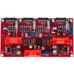
- TDA7293 Parallel kit from ebay (modular/slave style, no lossy emitter resistors)