My Corona Virus Build
First, a very public THANK YOU to DanielWritesbac2, his patience with noobs like me, perseverence and dedication inspired me to do this as my first (successful) electronics project.
Also, thanks to social distancing, and work-from home, I've been able to get back to this project which I first saw in 2015. I also compared a couple of single-chip pre-built boards from Ebay that gave me crappy distortion numbers (I could hear it!) so I know this board and these component values deliver on the promise of good sound for just a few $$$.
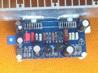
I used a 3.3 Film capacitor at the Input, because it's the largest I could find that would fit on the board.
Here I used a simple 25K resistor...for simplicity, and because I could not find an easy way to add the 100K VR along with the 39K resistor... I feel I could use a bit more midrange to boost voices... so I might try a 22K next.
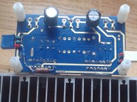
See Photo of bottom of board to see how I did this... Had to thread a few length of wire insulator on to the legs to keep the VR from touching the exposed traces. I also have the two pairs of 220 uF capacitors stacked vertically, and use the single pin from the V+ and V- power diodes to connect to the PSU.
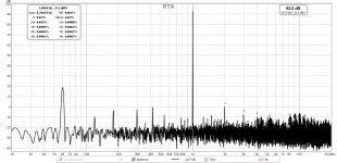
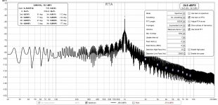
First I listened to music with my son and Daughter-in-law (young ears, you know?) and we all agreed the sound was great. Then I used XRK971's REW distotion analyzer rig to measure the amp. It has better numbers than my CARVER M500!!!
I am working on posting a diagram of the board showing how the schematic maps on-to it, and will also try to attach a mouser BOM.... THIS IS FUN!!!
Six.
P.S. I did deviate a little from the schematic and used 100 uF for the Feedback capacitor with a 1uF film stacked trackside. I got that idea from Dibya's TDS7293 Xmas amp by Jhofland
First, a very public THANK YOU to DanielWritesbac2, his patience with noobs like me, perseverence and dedication inspired me to do this as my first (successful) electronics project.
Also, thanks to social distancing, and work-from home, I've been able to get back to this project which I first saw in 2015. I also compared a couple of single-chip pre-built boards from Ebay that gave me crappy distortion numbers (I could hear it!) so I know this board and these component values deliver on the promise of good sound for just a few $$$.
The 105, 1uF box cap is your input cap, but there's other fun options to use, such as 4.7uF (or smaller) Elna Cerafine paralleled with a tiny polyester (to DIY your own low cost blackgate), etc. . . Try some variety and choose which you like.
I used a 3.3 Film capacitor at the Input, because it's the largest I could find that would fit on the board.
Resistor values: The leftmost 22K resistor is Input Load. Valid range is from 15k to 28k. A difference in value can alter the midrange loudness. If you don't need the adjustable feature shown in the schematic with 100kVR||39k, then just use a simple 22k or 25k resistor for input load.
Here I used a simple 25K resistor...for simplicity, and because I could not find an easy way to add the 100K VR along with the 39K resistor... I feel I could use a bit more midrange to boost voices... so I might try a 22K next.
The gain divider is the factory standard 22K/680R and although this will work, I disagree with bad performance that generic values cause. Instead, I would like to use 27K/730R for great quality. If you want quality results, the feedback resistor and the feedback-shunt resistor(s), MUST be placed underneath the board, close to the FB-Shunt cap. The feedback resistor is installed from pin14 to pin2. The feedback shunt resistor(s) are installed from pin2 to FB-shunt cap.
See assembly photos starting at post#24
See Photo of bottom of board to see how I did this... Had to thread a few length of wire insulator on to the legs to keep the VR from touching the exposed traces. I also have the two pairs of 220 uF capacitors stacked vertically, and use the single pin from the V+ and V- power diodes to connect to the PSU.
First I listened to music with my son and Daughter-in-law (young ears, you know?) and we all agreed the sound was great. Then I used XRK971's REW distotion analyzer rig to measure the amp. It has better numbers than my CARVER M500!!!
I am working on posting a diagram of the board showing how the schematic maps on-to it, and will also try to attach a mouser BOM.... THIS IS FUN!!!
Six.
P.S. I did deviate a little from the schematic and used 100 uF for the Feedback capacitor with a 1uF film stacked trackside. I got that idea from Dibya's TDS7293 Xmas amp by Jhofland
Attachments
Last edited:
Nice work, Sixto!
Thanks for the distortion measurement - it shows what I suspected, that the TDA7293’s quasi complimentary output DMOS stage makes dominant second harmonic with descending higher orders. Glad you are making use of REW for measurements.
Dibya’s Xmas amp will probably measure similarly and I may not bother to measure now.
OH yes. Maybe they are needed for protecting the speaker if the imbendance is 2ohm or lowest, from high power output of the 5 parallel pcb. Because in 3 Parallel pcb the resistors are missing. DunnoI was afraid of that. The TDA7293 chip doesn't need these resistors that are mandatory elsewhere for current balancing reasons.
Best regards!
Dibya's amp is looking good X!
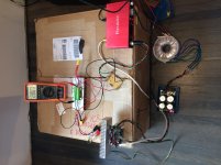
I'm not having as much luck... just tried running a distortion plot with parallell 8-ohm resistors for a 4-ohm total load, and I got a lot of noise, and a lot of heat, both at the amp heatsink, and the resistors heatsink. I think maybe the way I connected the resistors is giving me some weird results (oscillation?) . Photos and distortion plot attached.
I was expecting worse distortion at 4 ohms than 8 ohms but not the level of noise or possible oscillation I'm seeing. Curious about any suggestions folks may have to track down the source of noise?
Six.
P.S. Nope - something else is wrong... went back to the 8-ohm setup and I'm getting similar readings... too noisy!
Attachments
Last edited:
Hi Sixto
at your attenuation board i see 3 cable going into the focusrite box for the THD measurement but i miss the "GND" at the other side......or not?
maybe this fit to your use:
8:56
Discrete audio amplifier project PT20 Measuring distortion with computer - YouTube
chris
at your attenuation board i see 3 cable going into the focusrite box for the THD measurement but i miss the "GND" at the other side......or not?
maybe this fit to your use:
8:56
Discrete audio amplifier project PT20 Measuring distortion with computer - YouTube
chris
Looking into sudden noise & distortion...
Well, I've determined the USB interface is not the issue, and neither is the attenuator with the 3 wires to the Mic-in plug though I will look at grounding that back to something... (Plugged the Carver M500 back in, and it performed just fine with the same setup... plus I can hear the extra noise and distortion the TDA7293 puts out when I listen through a speaker) I looked through the board, and it was clean... checked all the solder joints, and made sure the 200r VR pins were well insulated from any ground traces on the board. No luck.
I'm afraid I may have done something to the TDA chips (maybe I got some bad clone chips?) so I will try to desolder and install 2 new chips. Now that I'm back to work after the holidays, I only have time to play on the weekends! :-(
Does anyone know if there is a way to test the pins on a TDA7293 V6 chip to see if everything is fine inside?
Six.
Here is another parallel TDA7293 board, I don't think I have seen this one posted before,
Another Aliexpress 2 x TDA7293 layout
Another Aliexpress 2 x TDA7293 layout
Another one as well:
https://www.kaltecs.com/100w-ultra-low-distortion-kit/
https://www.kaltecs.com/100w-ultra-low-distortion-kit/
Wow, I think I found the original article about the exact board this thread is about!
Original Article about this TDA7293 board from the 1st post
Original Article about this TDA7293 board from the 1st post
Hi all!
I was surfing the web looking for info about the tda7293 and I stumbled onto this juicy thread.
So maybe you can enlighten me about one thing.
In the data sheet are reported the high efficiency circuit and the modular (parallel) circuit. But not an high efficiency version of the modular circuit. Does this mean that a "class g" modular circuit is not feasible? I didn't find in the web such a circuit.
My knowledge of electronic doesn't go much beyond Ohm's law, so I can't evaluate by myself if such a circuit is possible and maybe I'm asking a stupid thing, but since I need (well...I'd like to have...) the power of the paralleled tdas I'd like to get that power with good efficiency too and the "class g" really fascinates me.
Any thoughts about?
Thanks.
I think this guy here did it - https://www.diyaudio.com/community/...e-paralel-for-best-sound.184102/#post-2894132Hi all!
I was surfing the web looking for info about the tda7293 and I stumbled onto this juicy thread.
So maybe you can enlighten me about one thing.
In the data sheet are reported the high efficiency circuit and the modular (parallel) circuit. But not an high efficiency version of the modular circuit. Does this mean that a "class g" modular circuit is not feasible? I didn't find in the web such a circuit.
My knowledge of electronic doesn't go much beyond Ohm's law, so I can't evaluate by myself if such a circuit is possible and maybe I'm asking a stupid thing, but since I need (well...I'd like to have...) the power of the paralleled tdas I'd like to get that power with good efficiency too and the "class g" really fascinates me.
Any thoughts about?
Thanks.
@Sixto and @xrk971 Thanks guys for publishing the distortion data. This is what I was missing in this otherwise great thread. What I wanted to say is that we have seen proposed modifications without a proof of their advantages.
On the snapshots below two measurements of unmodified stock design with a single IC are presented.
Measurement conditions:
Power supply: +/-35V, CRC
Sound card: Xonar U7 MK2
Dummy load: 4 parallel 22R, 100W resistors:
Heat sink: SK 56/100/SA (0.4K/W)
No smoothing and averaging has been applied to the measurement to avoid "better" results
By using rather large dummy load I was able to torture the IC at long high constant power output runs without the risk of thermal destruction.
It is important to note that besides low THD I was able to attain low noise too.
Also, another important conclusion is, that it is possible to attain Hi-Fi quality by using stock design on wide range of output power. For example: at 10VRMS (18.2WRMS), THD and THD+N were 0.0015% and 0.0064%, respectively. At higher power output both THD and THD+N have remained consistently at low level reaching values of 0.0060 and 0.0071 respectively in the proximity of clipping point at 20VRMS (72WRMS).
Conclusion: with proper PCB layout, stock design may result in respectable performance.
Fig. 1. ) 10VRMS
Fig. 2. ) 20VRMS
@Yantsov
Datasheet is clear: "Ref. Fig 12" . Different layout may result in different values. But note that the deviation from the published data are negligible and may have no impact on the sound whatsoever.
I have compared several PCBs and this one was the winner. The board from the OP, without the proposed modifications wasn't that good though, theoretically, it should have been better.
Theory is fine but actual measurements reveal the truth.
PS: Over the past few months I've been learning how to reduce the noise andit paid of, obviously. Now I can focus to my two major projects which I have put on hold while learning: Wolverine and Alpha Nirvana.
Last edited:
- Home
- Amplifiers
- Chip Amps
- TDA7293 Parallel kit from ebay (modular/slave style, no lossy emitter resistors)