Your twisted input wires are wrong.
If you want to use a star quad wiring connection, then the two diametrically opposed wires are one pair to connect the Hots and the other two diametrically opposed wires are the other pair to connect the Colds/Returns.
Hi Andrew, this is new to me. Can you please further explain this to me?
Thanks, and regards.
Pemo
In this picture ...
The twisted wires are:
Green Twist is hard soldered to the ground pin on 3.5mm socket, that is then tied to a star ground. The orange wire is soldered to the other side of the 3.5 mm plug, and although not seen, a blue wire twist was also added.
When I got around to hooking up the other side, I added a second green twist to ground, and a blue twist to the other side, and paid closer attention to left and right.
As this is temporary, the power wires have no twist at all, but when I get around to putting this into a final chassis a three pair twist sounds good, I will heat shrink both ends to help keep the twist.
The speaker wires also have no twist at all but it's cheap wire, and they are really a just in my test bed. They really cant be twisted as the red and the black casing are fused side by side. Easily broken into individual wires, and I am using them that way for some of the hookups.
I'm getting sound out of both channels, and its even, on power up with no source attached, no pops, cranked to full volume, ear against speaker, no hiss. Amazingly quiet.
From the photos I have looked at, of tidy builds, what Andrew is saying makes sense. As I go, my test bed improves all the time.
Next trick I think will be adding twisted pairs for the internal speaker connections, and moving to a blue/white setup rather than the red black. The Red/Black is what I happened to have around at the time.
Next trick I think will be adding twisted pairs for the internal speaker connections, and moving to a blue/white setup rather than the red black. The Red/Black is what I happened to have around at the time.
One more issue, the twisted wire is salvaged from a cat 5 cable, and without using a pair, there is really not enough structural integrity to make the wires work. On re-reading, that is a confusing point in my wring scheme.
Left/Right are each twisted pairs, but not twisted together, in the test bed. If I continue to use that recovered wire, it should also be twisted into a singleton with 4 total wires in each run ....
If I really do understand Andrews point!
Left/Right are each twisted pairs, but not twisted together, in the test bed. If I continue to use that recovered wire, it should also be twisted into a singleton with 4 total wires in each run ....
If I really do understand Andrews point!
Hi.
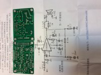
Just received a lm3886 kit from chinese seller. The circuitboard and scematics are attached. The only differences from scematics are input cap (2.2uF) and "big" power capacitors (220uF).
1) Any suggestions on this desing? Looks very simular to the reference lm3886 circuit, but maybe i missed something?
2) Where i should disconnect the signal ground from power ground on this board?
P.s: sorry for my english, it's bad, i know.
Attachments
Hi all. I do not want to hijack this thread. I have purchased the XY3886 kit from ebay just to play around with...
Would this transformer be okay to build with. I have a feeling it is too small...AS-1220 - 100VA 20V Transformer - AnTek Products Corp
I had it for another project but I am dying to see how this amp sounds with my LXmini clones.
Edit:: As I continue to read I see that a 200VA seems to be a minimum. I am going to look around my supply room and see what I have. I know that i have a couple of other transformers that I removed from older receivers (one Pioneer and one Rotel). I will see what they look like.
Thanks,
Wendell
Last edited:
- Status
- This old topic is closed. If you want to reopen this topic, contact a moderator using the "Report Post" button.
- Home
- Amplifiers
- Chip Amps
- 3886 Ebay kit Build