My obsevations
- LM3886 has lower distortion levels compared to TDA7293.
- TDA7293 is more forgiving on mistakes, doesn't blow easily.
- Connecting TDA7293 in parallel is trivial. So higher power on lower impedances can be obtained very easily.
- TDA7293 features a lower power dissipation scheme with dual power supplies.
panson_hk,
By any chance, have you compared two things between the LM3886 and the TDA7393?
1) Audio quality
2) Sturdiness (comments from DIYers blowing it are not too reassuring)
I was considering doing a parallel/bridged amp with 3886, but they seem to have some limitations. But I wonder why this TDA, which apparently can provide higher power, was not as successful as the 3886.
Maybe for being poor on things above. Is that so?
Hi,
I have not seriously compared their audio performance. From data sheet and my measurement, LM3886 has lower THD. You may take a look of my experiment in this thread http://www.diyaudio.com/forums/chip-amps/194511-lm3886-parallel.html.
I find that LM3886 is more fault forgiving. An advantage of TDA7293 is that output resistor is not needed for parallel operation.
Panson
I have not seriously compared their audio performance. From data sheet and my measurement, LM3886 has lower THD. You may take a look of my experiment in this thread http://www.diyaudio.com/forums/chip-amps/194511-lm3886-parallel.html.
Your last chart seems very interesting, where you power 3 and 4 parallel 3886 chips with +/-40v.
Perhaps that could be applied on 3886 kits like this:
NEW DIY LM3886 x 3 Mono Audio Power Amplifier Board | eBay
I find that LM3886 is more fault forgiving. An advantage of TDA7293 is that output resistor is not needed for parallel operation.
What about the gain on each 7293? Has it to be trimmed too to be equalized on all chips?
Has anyone this Yuanjing kit? It seems to be the same on all eBay sellers.
Sorry, the 7293 kit I was talking about:
TDA7293 Parallel 250W Mono Power Amp Board Kit NEW,Y25 | eBay
TDA7293 Parallel 250W Mono Power Amp Board Kit NEW,Y25 | eBay
Last edited:
Nice work there, want another config to test on the TDA7293/94 do mine http://www.diyaudio.com/forums/chip-amps/206591-tda7294-power-transistors-amp-tda7293-come-also.html
Would be nice to have some actual statistics on it, i have been using it (TDA7294) non-stop for 3+ Years now and it is REALLY REALLY good.
Would be nice to have some actual statistics on it, i have been using it (TDA7294) non-stop for 3+ Years now and it is REALLY REALLY good.
Please, give the PCB on two, three TDA7293 in paralel.
User Danielwritesbac recently posted about a 2x parallel TDA7293 amp board available on Ebay, completely assembled. It uses the master + slave configuration of this IC so that no output resistors are needed.
I would love to see this design extended to 4 ICs and made available (on Ebay).
-Charlie
Trick: Put 220uF caps closely to the pre power pins of these chips and provide clean power. They will put so much less power into the heatsink that a surprising amount more power will then be available for the speaker. The dual and triple boards seems to attempt this. I do not know about the "seven" board.Danielwritesbac recently posted about a 2x parallel TDA7293 amp board available on Ebay, completely assembled. It uses the master + slave configuration of this IC so that no output resistors are needed. I would love to see this design extended to 4 ICs and made available (on Ebay).
-Charlie
Links:
Two parallel TDA7293
my build thread
Three parallel TDA7293
Seven parallel TDA7293
You can point to point for 4 chips:
First:
Mount 4 chips across the heatsink with thermal paste and pads. Bend all of the v- pins up near the chip face and install a rail across all 4 chips. Bend all of the v+ pins up Half that far and install a rail across all 4 chips.
Next:
The power ground rail is held by the following caps. . . Install some 220uF caps on the rails. Install some 47nF caps in opposing order on the rails. This makes a very rigid assembly in short order. Well, just like this concept except bigger and you'll need more caps since you have more chips. Add one 2uF 250v cap from v+ to v- at the same place where you attach power cable.
And:
Jumper all of the mute together and give it v+ via 12k. Jumper all of the standby together and give it v+ via 22k. Connect a 10uF or larger from standby to power ground rail. Follow the datasheet to finish up the slave chips. Hook up the boostrap cap (47u*4chips= use 220uF), and finish up the pilot chip like a standard op amp. Add some large capacitance quite close to the amp to help it manage the speaker return force.
Maybe the point to point takes 20 minutes?
Then again, the price for that 7 chip kit is really similar to the Mouser price for 4 chips. Of course soldering a seven chip kit will take a heck of a lot longer.
")
Unfortunately elevators in China don't stop on the 4th floor.
Other thoughts:
Be prepared to make a preamp--Bigger transformer for more powerful amplifier didn't make the computer bigger or more powerful. darnit!
Last edited:
Oh dear. I forgot to mention a couple of things with that point to point.
If you use 60/40 solder, the amp may self destruct in approximately a year (sooner or later). You'll need to paint contact points with Gel Flux every time and use an odd numbered electronics solder that doesn't turn dull when re-heated or jostled. The deal is that soldering point to point stuff that's already soldered (multiple connections) needs good electronics solder for firm, lasting connections (not 60/40).
Aluminum wire between transformer and rectifier is crucial for low offset, since copper wire near the transformer will make confounding offset discrepancies in center tap and dual secondaries transformers.
Generally, for non-inverting chip amplifier, a 10k input load resistor (range 12k to 10k or smaller value) is excellent for extra low DC offset every time, regardless of the feedback resistor value. Although not great for everything, a metal film resistor is great for input load.
NFB cap size is about 220uF to 330uF (when feedback shunt resistor is from 2.2k to 2.7k range--for example a gain setting with 62k/2.7k or any nearby values). However, if you had used a datasheet example with 680R (or 1k) for feedback shunt resistor, then factor UP how much inconveniently bigger your NFB cap will need to be so that extra low bass can pass. The size of this component regulates the low bass versus mid bass balance. You can choose warm or cold bass or a nice balance of both.
I mentioned the NFB cap size because I assume you're pushing some big woofers with that Quad Parallel TDA7293, the on-chip limiter cuts biggest signals first and that datasheet has illustrated a bass blocker in ST's erroneous schematics. I think you'll want to adjust that. Unlike the datasheet, the chip itself is capable of excellent clear powerful bass.
If you use 60/40 solder, the amp may self destruct in approximately a year (sooner or later). You'll need to paint contact points with Gel Flux every time and use an odd numbered electronics solder that doesn't turn dull when re-heated or jostled. The deal is that soldering point to point stuff that's already soldered (multiple connections) needs good electronics solder for firm, lasting connections (not 60/40).
Aluminum wire between transformer and rectifier is crucial for low offset, since copper wire near the transformer will make confounding offset discrepancies in center tap and dual secondaries transformers.
Generally, for non-inverting chip amplifier, a 10k input load resistor (range 12k to 10k or smaller value) is excellent for extra low DC offset every time, regardless of the feedback resistor value. Although not great for everything, a metal film resistor is great for input load.
NFB cap size is about 220uF to 330uF (when feedback shunt resistor is from 2.2k to 2.7k range--for example a gain setting with 62k/2.7k or any nearby values). However, if you had used a datasheet example with 680R (or 1k) for feedback shunt resistor, then factor UP how much inconveniently bigger your NFB cap will need to be so that extra low bass can pass. The size of this component regulates the low bass versus mid bass balance. You can choose warm or cold bass or a nice balance of both.
I mentioned the NFB cap size because I assume you're pushing some big woofers with that Quad Parallel TDA7293, the on-chip limiter cuts biggest signals first and that datasheet has illustrated a bass blocker in ST's erroneous schematics. I think you'll want to adjust that.
Unlike the datasheet, the chip itself is capable of excellent clear powerful bass.Aluminum wire between transformer and rectifier is crucial for low offset, since copper wire near the transformer will make confounding offset discrepancies in center tap and dual secondaries transformers.
Daniel
I have never heard this before, what attributes does the aluminum wire bring to this.
I would think aluminum wire would be very difficult to attach, cause a severe reliability loss, and possibly be even dangerous.
If some resistance is desired I would think that there are other possibilities or materials including smaller gauge copper.
Thanks
Antonio
I should have said alloy. Fortunately, a nice alloy wire comes free/attached with most transformers. Other transformers have connection tabs at the top and copper wire is okay there (just not draped/tangled near the transformer coil's field).Daniel
I have never heard this before, what attributes does the aluminum wire bring to this.
I would think aluminum wire would be very difficult to attach, cause a severe reliability loss, and possibly be even dangerous.
If some resistance is desired I would think that there are other possibilities or materials including smaller gauge copper.
Thanks
Antonio
But, if one were to alter a center tap to a dual secondaries by cutting the link and attaching wires, there could be a ~1v discrepancy that leads to DC offset. This will happen with a single bobbin transformer. Usually there's enough of the factory provided cable to get the job done. But if somebody threw that cable out, it would be a mistake.
As you can see, the problem does not happen often. Most people who need a dual secondaries transformer will simply buy it. And then, no problem.
Last edited:
What is the correct name of that all silver color alloy wire that comes attached as the lead wires for transfomers?. . . And ignore the bits you can't understand.
It could be tin (Sn) coating, or it could be solder (Sn+Pb) coating, or it could be leadless solder coating (lot's of formulations).
The wire should be copper in all normal applications.
Aluminium could be used where low weight is critical.
Silver could be used where extra cost is advantageous.
Have you ever looked further up the wire to see what is coating the lead outs beyond the tinned ends?
Have you ever scraped the leadouts to find what colour is under the tinning?
Last edited:
Well, I checked 3 hammond, 2 antek and 2 stancor.
Stripping the wires back, the color is the same as the tinning.
When scraping, the color under the tinning is the same as the tinning.
Cutting into the wires, the inside color is the same as the tinning.
The majority of this alloy material is not copper.
Stripping the wires back, the color is the same as the tinning.
When scraping, the color under the tinning is the same as the tinning.
Cutting into the wires, the inside color is the same as the tinning.
The majority of this alloy material is not copper.
Big Current Buffer??????
The most interesting section of this thread starts with Panson at post 12 and then Abraxalito at post 18.
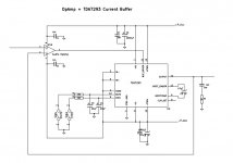
I wonder if any TDA7293's have been employed as a current buffer for an external op-amp or maybe even a tube or discrete? I may be off the mark, but it looks like you can paste the TDA7293 current buffer section onto the output of your favorite headphone amp and then proceed to drive speakers with it. Has anyone made such a composite?
The most interesting section of this thread starts with Panson at post 12 and then Abraxalito at post 18.
I wonder if any TDA7293's have been employed as a current buffer for an external op-amp or maybe even a tube or discrete? I may be off the mark, but it looks like you can paste the TDA7293 current buffer section onto the output of your favorite headphone amp and then proceed to drive speakers with it. Has anyone made such a composite?
It has been a long time since my last post of this thread. In this summer time, I want to continue this project. I will evaluate an opam + TDA7293 buffer in a unity-gain configuration as sketched in the attached figure.
Attachments
Last edited:
- Status
- This old topic is closed. If you want to reopen this topic, contact a moderator using the "Report Post" button.
- Home
- Amplifiers
- Chip Amps
- TDA7293 single, bridge, parallel